
BLOG
- Home
- BLOG
- Grinding Applications
- CNC Grinding Machines for Hydraulic Valve Spools
CNC Grinding Machines for Hydraulic Valve Spools
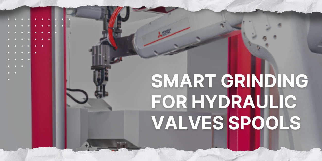
Precision grinding of hydraulic valve spools is one of the most demanding processes in hydraulic component manufacturing. Whether in industrial machinery, automotive transmissions, or precision instruments, the spool-to-bore diametral clearance must typically be held within 1 to 3 μm. Even small deviations can reduce system efficiency—or cause internal leakage and unexpected downtime.
High-precision grinding for hydraulic components requires far stricter machine specifications than standard cylindrical grinding. With the right CNC grinding machine, automated gauging, and match-grinding capability, manufacturers can reliably hold tight tolerances on spool cylindricity and straightness—even at high production volumes.
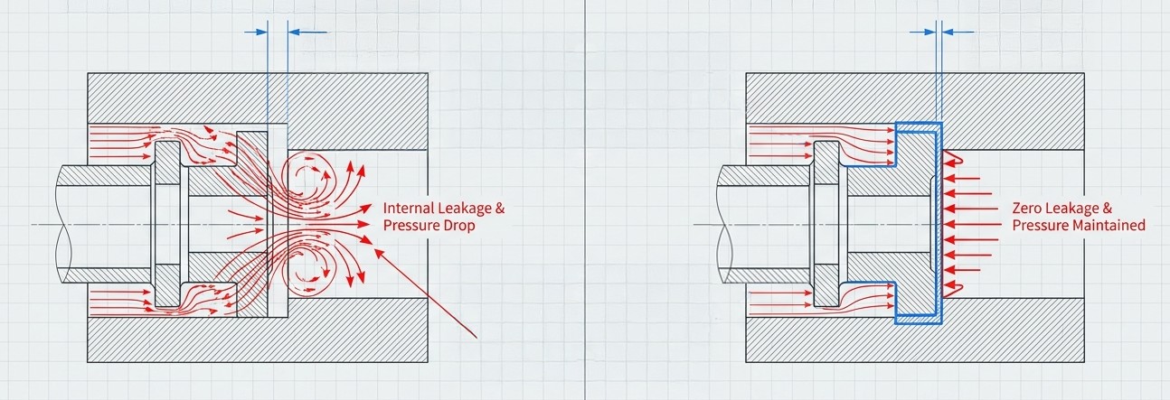
Hydraulic systems use oil as a medium to convert electrical or mechanical energy into pressure energy via hydraulic pumps, powering a wide range of machinery. To maintain stable operation, high-pressure hydraulic oil must pass through multiple control components that regulate pressure and flow. Among these, the precision of the hydraulic valve is critical. High-accuracy clearance fits between the valve spool and body ensure tight sealing and accurate flow control—making them key to the overall performance and reliability of the system.
〈Further Reading: GRINDING MACHINE: essential for precision machining in manufacturing industry〉
.jpg)
Choosing the Right CNC Grinder for Hydraulic Valve Spools
In hydraulic component manufacturing, spool grinding is the process that most directly determines sealing performance and control accuracy. Before selecting a machine, clarify three key requirements: spool material (alloy steel vs. heat-treated steel), geometric tolerance specifications (cylindricity, roundness, and straightness), and production volume (high-mix low-volume vs. mass production). These three factors determine which type of CNC grinding machine is the right fit:
-
CNC Cylindrical Grinding Machines: Ideal for hydraulic valve spools with center holes. These machines deliver high-precision OD grinding to meet sub-micron roundness, cylindricity, and concentricity requirements—critical for handling interrupted cuts on spool lands, metering edges, and control grooves.
-
CNC Centerless Grinding Machines: Best suited for high-volume mass production. Where cylindrical grinders offer process flexibility for high-mix low-volume runs or match grinding, centerless grinders deliver higher throughput while maintaining stable dimensional tolerances.
-
CNC Internal Grinding Machines: Required when valve body bores must meet tight dimensional and roundness tolerances—typically within a few microns. Internal grinders ensure high-precision ID grinding to achieve the exact clearance fit between spool and body.
〈Further Reading: Hydrostatic Technology: The Key to Stable Centerless Grinding〉
TOPKING CNC Grinder Selection Guide
Recommended Cylindrical Grinding Machine Models
Recommended Centerless Grinding Machine Models
- NC Centerless Grinder:H-4520-NC(thru-feed or in-feed grinding customization)
- CNC Centerless Grinder:H-4520-CNC(thru-feed or in-feed grinding customization)
〈Further Reading: NC vs CNC: The Key Role of 2NC Cylindrical Grinders in Between〉
Hydraulic Valve Spool Grinding Solution: TOPKING Recommends X-2540LM
(1).jpg)
The TOPKING LM Series CNC Cylindrical Grinding Machines feature a linear motor-driven cross slide, which improves machine rigidity and stability while significantly reducing cycle time. Purpose-built for high-precision workpieces—including hydraulic valve components, automotive parts, and aerospace components—the LM Series delivers consistent accuracy across extended production runs.
1. CROSS-SLIDE: Optimizing Floor Space
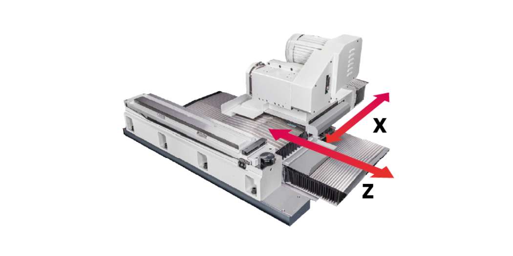
Unlike traditional grinding machines, the TOPKING X Series adopts a cross-slide design for the X and Z axes. The grinding wheel head is mounted on the cross slide, enabling precise X and Z-axis movement to accurately position the workpiece during grinding. The worktable is firmly fixed to the machine base and does not travel with the grinding components. This arrangement reduces the machine's footprint—making it well-suited for production environments where floor space is at a premium.
2. LINEAR MOTOR DRIVEN X-AXIS: Consistent and Reliable Production Quality
The TOPKING LM Series features a linear motor drive combined with high-precision linear guideways, eliminating mechanical friction and backlash in the feed motion. The X-axis uses a full closed-loop linear scale as standard, providing precise infeed accuracy and fast dynamic response.
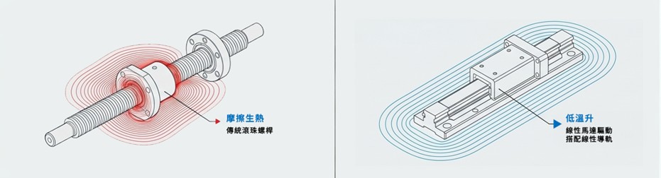
Compared to traditional ball screw systems, the linear motor drive has no mechanical contact and no belt drive—eliminating both friction-generated heat and vibration at the source. This simplifies the mechanical structure, reduces component count, and improves space utilization. The result is a machine that runs more stable, requires less maintenance, and delivers better process repeatability. Because the non-contact drive generates no mechanical wear, grinding consistency improves and machine service life extends, ultimately reducing long-term maintenance costs and the risk of unplanned downtime.
3. DUAL SYNCHRONOUS WORK SPINDLES: Preventing Clamping Distortion, Faster Changeovers
An optional dual-drive workhead and tailstock is available, using a dual-center synchronous drive system with an extendable spindle. This simplifies workpiece clamping, reduces fixture complexity, and removes the need to design for separate drive mechanisms.
The extendable spindle overcomes the travel limits of a conventional tailstock, allowing the machine to quickly adapt to different workpiece lengths. This cuts tailstock adjustment time during changeovers and improves scheduling flexibility across varied part sizes.
〈Further Reading: How to Choose the Right CNC Grinder: Match the Control System and Machine to Your Production Needs〉
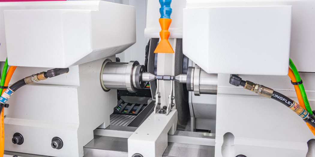
Automating Valve Spool Grinding
In modern precision grinding for hydraulic valve spools and bodies, automation now extends beyond material handling to include real-time quality inspection and dynamic machining parameter adjustment. TOPKING's automation solution supports smart manufacturing through three integrated steps:
1. Real-Time Measurement Feedback
A robotic arm loads the valve body and performs precise ID measurement. The captured data is immediately transmitted to the CNC grinding machine's controller.
2. Smart Match Grinding
The system picks the hydraulic valve spool and positions it in the machining zone. Based on the actual valve body ID from the previous step, the CNC controller dynamically adjusts the OD grinding parameters for that specific spool.
3. In-Process Gauging and Dimensional Control
During grinding, advanced in-process gauging monitors the OD in real time, driving a linear motor for precise infeed control. Unlike post-process measurement—where parts are checked only after leaving the grinding zone—in-process gauging closes the feedback loop during the cut, enabling immediate compensation without waiting for a batch to complete. This ensures every spool-and-body pair achieves a micron-level clearance fit, minimizing the risk of internal leakage.
Automation does more than boost capacity—it directly improves yield rates and machine utilization (OEE). That said, even well-integrated automation depends on the machine's underlying dynamic rigidity and thermal stability under high-precision demands. These are the core technical factors covered in the next section.
This solution also integrates dual synchronous work spindles and a tailstock to reduce non-productive time during loading, unloading, and part changeovers—helping customers build a stable, efficient automated grinding line.
Achieving Precision in Valve Spool Grinding: Core CNC Machine Advantages
When selecting a CNC grinding machine for hydraulic valve spools, dynamic rigidity and thermal stability deserve as much attention as automation capability. Below are the key engineering features designed to address the three most common challenges in spool production:
1. Suppressing Chatter from Interrupted Cutting
Hydraulic valve spools feature multiple spool lands, metering edges, and control grooves along their OD—creating frequent interrupted cutting as the grinding wheel engages and disengages with these surfaces at high speed. The resulting impact forces can trigger micro-chatter, degrading surface roughness and causing localized geometric deviation on the very edges that determine flow control accuracy.
To counter this, the machine uses a cross-slide structure and a high-rigidity cast-iron base that absorbs impact and dampens vibration. The result is stable surface finish quality and consistent geometry across the entire production run.
2. In-Process Wheel Dressing and Size Compensation
Valve spools are commonly made from high-hardness alloy steel or heat-treated materials, which accelerate grinding wheel wear. As wheel geometry shifts, spool cylindricity and straightness begin to drift.
The machine includes an in-process wheel dressing and compensation system, configurable with single-point dressers or rotary diamond rollers depending on process requirements. Within the automated machining cycle, the wheel is dressed at set intervals while the controller applies real-time dimensional offsets—keeping the wheel sharp and the output accurate throughout the run.
3. Thermal Displacement Control
During extended high-speed operation, heat from drive system friction and coolant temperature fluctuations causes micro thermal expansion in the machine structure. For match-grinding applications with tight clearance fit requirements, this thermal drift is the leading cause of batch-to-batch variation.
Specific models—such as the X-LM Series—address this by using linear motor drives, which eliminate the heat generated by ball screw friction. Reducing drive system heat output helps the machine maintain thermal equilibrium, ensuring consistent spool dimensions across continuous production shifts.
〈Further Reading: The Precision Revolution in Non-Round Grinding: Why Linear Motors are the Only Choice for Crankshaft and Camshaft Machining〉
FAQ: CNC Grinding for Valve Spools
1. What should I look for in a CNC grinding machine for hydraulic valve spools?
The most important factor is geometric tolerance stability. A high-rigidity machine bed and feed axes with full closed-loop control are baseline requirements. Because hydraulic valve spools demand strict clearance fits, cylindricity and straightness tolerances leave almost no margin for error. Look for machines with high-precision optical scales and a cross-slide design—this structure provides the mechanical rigidity needed to suppress machining chatter and maintain dimensional consistency in mass production.
2. Why does thermal expansion cause dimensional variation in precision valve spool grinding?
As the machine heats up during continuous operation, thermal expansion shifts workpiece dimensions and disrupts the precise clearance fits required for batch consistency. Heat from drive system friction and the grinding zone itself are the primary sources. When evaluating a CNC grinder, pay attention to how the feed axes manage heat. Models that use linear motor drives rather than ball screws run at lower temperatures, helping the machine maintain thermal equilibrium and dimensional stability across long production runs.
3. Can a CNC grinder hold consistent surface finish on valve spools with control grooves?
Yes—but the key is structural rigidity and servo response speed. Spool lands, metering edges, and control grooves on hydraulic valve spools generate repeated impact forces during grinding. A well-built CNC grinder uses a high-rigidity cast-iron structure to absorb these micro-vibrations, consistently meeting surface roughness and geometry requirements even under interrupted cutting conditions.
Conclusion
The machining tolerances for hydraulic valve spools leave very little room for error—any compromise in machine selection tends to show up as quality variation in mass production. For manufacturers, choosing the right CNC grinding machine is more than a procurement decision. It is a commitment to line stability and total cost of ownership over the long term.
By combining linear motor drives, a cross-slide structure, and closed-loop dimensional compensation in automated grinding lines, TOPKING machines help customers maintain consistent spool-and-body diametral clearance fits at scale.
If you are evaluating cylindrical grinding options or looking to upgrade your production line to a fully automated solution, contact us. We can recommend specific machine models and arrange grinding trials based on your workpiece specifications and production volume.
〈Further Reading: Struggling with Inefficient Grinding Operations?〉
.jpg)


TOPKING Technology
TOPKING Technology Co., Ltd., established in 2007, is a Taiwan-based manufacturer specializing in advanced precision grinding machines. With expertise in R&D, manufacturing, technical consulting, test grinding, training, and after-sales service, TOPKING provides high-quality cylindrical grinders, cross-slide cylindrical grinders, special-purpose grinding machines, and hydrostatic centerless grinders for industries such as automotive, aerospace, medical devices, and precision machinery worldwide.
Article Classification
Recent Articles
- What Is Centerless Grinding? Principles, Comparisons, and Process Selection
- What Is a Grinding Machine? Principles, Types, and Differences from Lathes and Milling Machines
- Overcoming Deformation in High-Aspect-Ratio Shafts: Practical Advantages of 30° Angular Grinding in Agricultural Output Shafts
- CNC Grinding Machines for Hydraulic Valve Spools
- Grinding Machine Explained: Principles, Types, and Applications