
BLOG
- Home
- BLOG
- Grinding Basics
- What Is a Grinding Machine? Principles, Types, and Differences from Lathes and Milling Machines
What Is a Grinding Machine? Principles, Types, and Differences from Lathes and Milling Machines
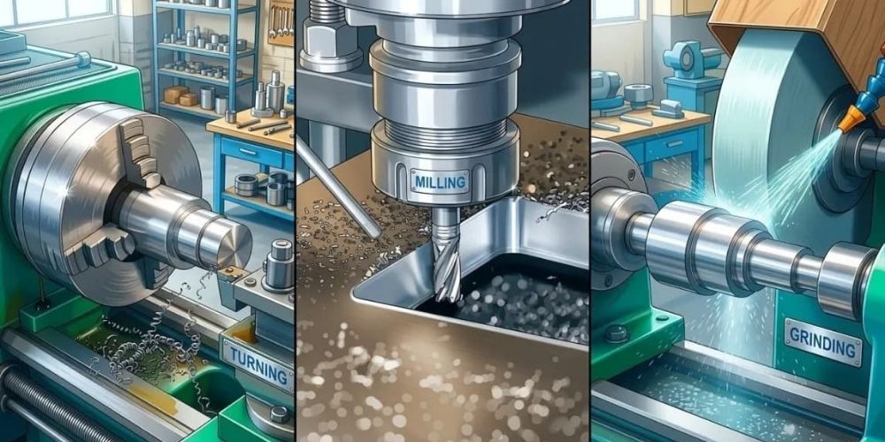
In metalworking, lathes, milling machines, and grinding machines are all essential machine tools, but each serves a different role in the manufacturing process. Lathes and milling machines are mainly used for material removal and creating the basic shape of a workpiece, while a grinding machine focuses on precision finishing by correcting dimensions, improving roundness, and achieving the required surface finish.
When a workpiece undergoes heat treatment and experiences dimensional changes, or when the application requires micron-level tolerances, high roundness accuracy, and strict surface quality control, conventional cutting processes may no longer be sufficient. In these cases, a grinder becomes a critical machine tool for precision manufacturing.
This article explains the working principles of grinding machines, common grinder types, and the differences between grinding, turning, and milling processes to help manufacturers select the most suitable machining method based on their workpiece requirements.
What Is a Grinding Machine? Understanding the Grinding Process for Precision Machining
A grinding machine is a precision machine tool that removes material using a high-speed rotating grinding wheel. Unlike lathes and milling machines, which rely on cutting tools to remove material, a grinder uses abrasive grains on the grinding wheel surface as microscopic cutting edges to achieve controlled material removal.
Because the amount of material removed during each grinding pass is extremely small, grinding machines are particularly suitable for machining hardened materials after heat treatment, such as hardened steel, bearing steel, and tool steel. They are also commonly used as the final finishing process in manufacturing to achieve tight dimensional tolerances, improved roundness, and the required surface roughness.
How Does a Grinding Machine Work?
The grinding process mainly relies on a high-speed rotating grinding wheel to perform precision material removal. The surface of a grinding wheel consists of thousands of abrasive grains, and each grain acts as a small cutting edge.
When the grinding wheel rotates at high speed and comes into contact with the workpiece, these abrasive grains continuously remove a very small amount of material. This controlled removal process gradually brings the machined surface closer to the dimensions and surface finish specified on the engineering drawing.
Compared with turning or milling, the depth of cut in grinding is typically much smaller, generally around 0.001-0.01 mm per pass.This makes grinding especially suitable for correcting dimensional changes after heat treatment while improving dimensional accuracy, roundness, and surface roughness.
How Is the Grinding Process Completed?
The grinding process involves three primary actions that occur simultaneously:
-
Grinding Wheel Rotation: Providing the Grinding Action
The grinding wheel consists of abrasive grains bonded together by a bonding material. During high-speed rotation, the abrasive grains contact the workpiece surface and remove material through microscopic cutting action.
The grinding wheel specification, including abrasive type, grain size, hardness, and wheel dressing condition, directly affects grinding performance, machining efficiency, and final surface finish.
-
Workpiece Feed — Controlling Material Removal and Grinding Position
Depending on the grinding method, the workpiece either rotates or moves while the grinding wheel gradually processes the required area. Different grinder designs use different workpiece support and movement methods, which determine their suitable applications.- Cylindrical grinding: The workpiece rotates between centers or with suitable fixtures while the grinding wheel performs external diameter grinding along the workpiece axis.
- Centerless grinding: The workpiece is supported by a work blade and positioned between the grinding wheel and regulating wheel. The difference in wheel speeds controls workpiece rotation and feed during continuous grinding.
By controlling feed rate, grinding wheel condition, and grinding path, the amount of material removed can be maintained consistently to achieve the required machining accuracy.
-
Coolant Circulation — Controlling Grinding Heat
During grinding, the high-speed contact between the grinding wheel and workpiece generates grinding heat. Coolant is used to reduce the temperature in the grinding zone, remove grinding debris, and prevent thermal deformation that may affect dimensional stability.A properly designed coolant system also helps reduce wheel loading and extend grinding wheel life. For high-precision machining applications, coolant management is an important factor in maintaining consistent dimensional accuracy.
How Does the Self-Sharpening Characteristic of a Grinding Wheel Affect Grinding Performance?
A grinding wheel has a natural self-sharpening characteristic during the grinding process. As abrasive grains gradually become worn, some grains break away under cutting pressure, exposing new sharp abrasive edges that maintain the wheel’s cutting ability.
However, continuous machining will eventually change the wheel profile and reduce grinding performance. Regular wheel dressing is therefore required to restore the wheel geometry, remove worn abrasive grains, and maintain stable grinding accuracy and surface finish.
Grinding Accuracy Metrics to Check Before Choosing a Grinder
Surface roughness parameters are commonly defined according to the ISO 4287 and ISO 4288 surface texture standards. Among them, Ra, Rz, and Ry (or Rmax) are frequently referenced on engineering drawings and used during quality inspection.
In grinding applications, the required surface roughness is usually determined by the function of the component. For example, rotating contact surfaces require control of friction and wear, sealing surfaces require stable contact conditions, and precision sliding surfaces require consistent movement performance.
Ra (Arithmetic Mean Roughness)
Ra is the most commonly used surface roughness parameter. It represents the average deviation of the surface profile from the mean line over the measured length, providing an overall evaluation of the ground surface condition.Ra is widely used for evaluating general contact surfaces, sliding surfaces, and rotating components where consistent surface finish is required.
Typical Applications:
- Bearing rollers: Bearing rollers operate under continuous rolling contact. The surface finish of the ground outer diameter directly affects running smoothness and wear behavior, making Ra control an important part of the manufacturing process.
- Motor shafts: The bearing fitting area of a motor shaft requires accurate dimensional tolerance and roundness. In addition, the ground surface condition plays an important role in achieving stable assembly and reliable operation.
Rz (Ten-Point Mean Roughness)
Rzrepresents the average height difference between the five highest profile peaks and the five deepest profile valleys within the sampling length. Unlike Ra, which reflects the overall average surface roughness, Rz is more sensitive to significant surface irregularities. Therefore, it is widely used to assess the surface quality and process stability of precision-ground components.
Typical Applications:
- Hydraulic valve spools: Hydraulic valve spools require precise sliding movement inside the valve body. Surface profile variations can affect clearance control and motion stability, so inspection may consider both dimensional accuracy and surface roughness characteristics.
- Precision fitted components: Components requiring stable and repeatable fits may require Rz evaluation in addition to Ra to better understand surface peak and valley conditions.
Ry / Rmax (Maximum Height of Surface Profile)
Ry, also commonly referred to as Rmax, represents the maximum vertical distance between the highest peak and lowest valley within the measured evaluation length. This parameter is mainly used to identify localized surface irregularities. For components where a single surface defect, raised area, or deep valley may affect performance, maximum height parameters provide additional quality information.
Typical Applications:
- Ball screws: The raceway surface of a ball screw supports continuous movement of recirculating balls. In addition to dimensional and geometric accuracy, high-precision applications may also consider maximum surface height variations that could affect motion smoothness.
- Precision guideways: Precision guideways require stable sliding performance and positioning accuracy. Local surface defects may increase friction or affect movement consistency, making maximum height parameters a useful reference during quality evaluation.
Ra, Rz, and Ry(Rmax) are not interchangeable parameters. Each evaluates surface characteristics from a different perspective.In actual grinding applications, surface roughness is not evaluated alone. It must be considered together with dimensional tolerance, roundness, cylindricity, and the functional requirements of the component to determine the appropriate grinding process and machining conditions.
.jpg)
Grinding Precision Grades
Grinding accuracy requirements vary depending on the function of the component and the required quality level. In general, grinding processes can be categorized into three levels: general grinding, precision grinding, and ultra-precision grinding.
- General grinding:
General grinding is the most common grinding application in manufacturing. It is mainly used to improve the dimensional accuracy and surface finish of components after turning or milling.
Typical applications include drive shafts, shaft mating surfaces, and general precision machine components. The main objective is to achieve stable dimensional tolerances and consistent surface finish requirements.
- Precision grinding:
Precision grinding requires tighter control of grinding parameters, including feed rate, grinding wheel dressing condition, and machining stability, to achieve improved dimensional accuracy and surface finish.
Typical applications include bearing components, hydraulic components, and precision mold parts. These applications generally require a grinder with higher rigidity, thermal stability, and process control capability.
- Ultra-precision grinding:
Ultra-precision grinding is applied to components with extremely demanding requirements for surface quality and dimensional stability.
The process requires careful control of machine accuracy, environmental conditions, grinding wheel condition, and coolant performance. Typical applications include optical components, semiconductor equipment parts, and precision measuring instruments.
Which grade you need depends on the part's function and quality requirements. General grinding covers the dimensional and surface finish needs of most precision parts; precision grinding suits parts with tighter fit requirements; ultra-precision grinding is reserved for the small set of parts that need exceptional surface quality and process stability.
A lower Ra value is not always the best solution. The ideal grinding condition depends on the component function, material characteristics, and operating requirements. The goal is to select the grinding process that provides the required performance and reliability for the application.
Grinding Grade Comparison
| Grinding Grade | Surface Roughness Ra | Tolerance Grade (IT) | Typical Application |
|---|---|---|---|
| General grinding | 1.25μm–0.16μm | IT8–IT5 | General precision parts, standard mating surfaces |
| Precision grinding | 0.16μm–0.04μm | IT7–IT5 | High-precision mating parts, bearings, molds |
| Ultra-precision / mirror grinding | Below 0.04μm | IT5 or tighter | Optical components, semiconductor equipment |
(Swipe left or right to view the full table.)
《Extended Reading: CNC Grinding Machines for Hydraulic Valve Spools》
Precision Differences Between Lathes, Milling Machines, and Grinders
When comparing machining equipment, Lathes, Milling Machines, and Grinders are often discussed together. Although all three processes remove material from a workpiece, they use different cutting methods, tooling systems, and machining strategies. As a result, their roles in dimensional control, surface finish, and part applications are different.
In general, lathes and milling machines are used for initial machining and part shaping, establishing the basic geometry and dimensions of a workpiece. Grinding is typically performed at the later finishing stage, where a grinding wheel removes a small amount of material to improve dimensional accuracy, geometric accuracy, and surface finish.
Lathe
A lathe uses a single-point cutting tool to machine a rotating workpiece. It is commonly used for cylindrical components, including external diameters, end faces, bores, threads, and stepped shafts.
Because turning provides high material removal efficiency, lathes are typically used during the early machining stage to quickly establish the basic shape and dimensions of a component. For shaft-type parts, turning is often the first machining process before additional finishing operations.With suitable tooling and cutting conditions, a lathe can also perform hard turning on certain heat-treated materials.
However, when a component requires tighter control of roundness, cylindricity, surface roughness or precision mating surfaces, turning alone may not consistently achieve the required results. In these cases, grinding is commonly used as the final finishing process to meet the required specifications.
Milling Machine
A milling machine uses a rotating multi-edge cutting tool to machine flat surfaces, slots, holes, stepped features, and complex profiles.Compared with a lathe, a milling machine provides greater machining flexibility and can process non-rotational components as well as features in multiple directions. This makes milling widely used for molds, jigs, fixtures, and structural machine components.
However, milling is primarily focused on creating part geometry and structural features through cutting. When the application requires improved surface finish, tighter fitting accuracy, or more stable dimensional control, a grinding process is often required to achieve the final quality requirements.
Grinder
A grinder,or grinding machine, is typically used during the final machining stage to refine workpiece dimensions, geometric accuracy, and surface condition through controlled abrasive material removal.
Unlike lathes and milling machines, which focus mainly on material removal and shaping, grinding is used to correct small dimensional deviations and improve the final accuracy of a component.
Grinding is commonly applied after previous machining operations and heat treatment, where it helps achieve tighter dimensional tolerances, improved roundness, better cylindricity, and the required surface finish.
For this reason, grinding is usually positioned as the final precision machining process, correcting remaining dimensional and form deviations from earlier operations and bringing the workpiece to its final drawing specifications.
Turning, Milling, and Grinding: Typical Tolerance and Finish
| Process | Tolerance Grade (General) | Surface Roughness Ra (General) |
|---|---|---|
| Lathe (finish turning) | IT10–IT7 | 6.3μm–0.4μm |
| Mill (finish milling) | IT8–IT7 | 6.3μm–0.8μm |
| Grinder | IT8–IT5 | 1.25μm–0.16μm |
Note: figures are standard reference ranges based on CNS B1001-3 and B1272. Actual values vary with machine specification, tooling, workpiece material, and process parameters.
Common Types of Grinding Machines: Comparing the 4 Main Types
Once you understand the role of grinding in the machining process, the next question is: which type of grinder is right for your workpiece? Among the many types of grinding machines,four common categories cover most industrial applications: cylindrical grinders, centerless grinders, surface grinders, and internal grinders.
Each type is designed for different workpiece shapes, production needs, and precision requirements.
Cylindrical Grinder: Precision Choice for Shaft Components
A cylindrical grinder — also called an OD (outside diameter) grinder — is used to finish the external cylindrical surfaces of a workpiece. During machining, the workpiece is typically supported between centers while the grinding wheel removes material from the outer diameter. This makes cylindrical grinders suitable for shaft components with stepped diameters, shoulders, tapers, or more complex cylindrical profiles.
Key Features: The workpiece usually requires center holes for mounting between centers. Cylindrical grinders are commonly used for single-piece production, small-to-medium batch manufacturing, and precision components requiring tight dimensional and geometric control.
Typical parts: drive shafts, machine tool spindles, camshafts, hydraulic cylinder rods, precision lead screws.
Industries: Machine tool manufacturing, Automotive drivetrain components, Aerospace precision components, Mold and die manufacturing
TOPKING Applicaion: TOPKING provides NC and CNC cylindrical grinders designed for applications ranging from standard shaft machining to complex precision grinding requirements, helping manufacturers achieve stable and repeatable grinding results.
《Extended Reading: The Precision Revolution in Non-Round Grinding: Why Linear Motors are the Only Choice for Crankshaft and Camshaft Machining》
Centerless Grinder: Efficient Solution for High-Volume Production
A centerless grinder is designed for continuous production of cylindrical components and differs from a cylindrical grinder mainly in how the workpiece is supported.Instead of being held between centers, the workpiece is positioned between the grinding wheel and regulating wheel, supported by a work rest blade. The speed difference between the two wheels controls workpiece rotation and automatic feed during grinding.
Key Features: Because center holes and workpiece clamping are not required, centerless grinders are highly suitable for continuous production and high-volume machining of cylindrical parts with relatively simple geometries.
Typical parts: screws, pins, valve stems, piston pins, hydraulic components, needle rollers.
Industries: Automotive fasteners, Electronic components, High-volume precision components, Hydraulic and pneumatic components.
TOPKING Applicaion: TOPKING develops NC and CNC centerless grinders for applications requiring stable dimensions, consistent roundness, and continuous production performance. These grinders are commonly applied in automotive components and precision industrial manufacturing.
《Extended Reading: How to Choose the Right CNC Grinder: Match the Control System and Machine to Your Production Needs》
Surface Grinder: Precision Grinding for Flat Surfaces
A surface grinder is designed for finishing flat surfaces with high flatness accuracy and controlled surface finish.During operation, the grinding wheel moves vertically toward the workpiece while the table moves back and forth, allowing material to be removed gradually until the required flatness and surface condition are achieved. For components requiring accurate flatness, parallelism, and precision mating surfaces, surface grinding provides a reliable finishing method.
Typical parts: Mold base plates, Guide rails, Gauges, Tool holders, Machine bases.
Industries: Mold and die manufacturing, Precision tooling, Measuring instruments.
Internal Grinder: Precision Machining for Internal Bores
An internal grinder, also known as an ID (internal diameter) grinder, uses a small high-speed grinding wheel to machine the internal surfaces of a workpiece.It is used for precision finishing of cylindrical bores, tapered bores, through holes, and blind holes. Internal grinding is especially suitable for applications requiring high concentricity, roundness, and internal surface finish.
Key Features:An internal grinder, also known as an ID grinder, uses a small-diameter grinding wheel to finish the inside surface of a workpiece. It is designed for cylindrical bores, tapered holes, and applications requiring high concentricity and internal surface quality.Because the grinding wheel size is limited by the bore diameter, machine rigidity, spindle performance, and wheel dressing conditions are important factors for achieving stable accuracy.
Internal grinders are commonly used for single-piece and small-to-medium batch production involving complex bore geometries and tight tolerances. They provide strong control over roundness, cylindricity, and internal surface finish.
Typical parts:Bearing housing bores, Hydraulic cylinder bores, Gear bores, Bearing rings, Spindle bores, Valve body bores.
Industries: Automotive manufacturing, Electronics, Mold and die manufacturing, and General machinery, Bearing production, Hydraulic components, and Aerospace precision parts
Quick Reference: Which Grinder Fits Your Part?
| Cylindrical Grinder | Centerless Grinder | Surface Grinder | Internal Grinder | |
|---|---|---|---|---|
| Grinding location | OD | OD | Flat surface | Bore |
| Center hole required | Yes | No | — | — |
| Batch size | Single piece to medium batch | Large continuous batch | Single piece to large batch | Single piece to medium batch |
| Typical parts | Drive shafts, spindles | Screws, pins | Mold base plates, guide rails | Bearing housing bores |
| Tolerance range | IT5–IT6 | IT5–IT6 | IT5–IT6 | IT5–IT7 |
| Main industries | Machine tools, aerospace | Automotive, electronics | Mold and die, metrology | Bearings, hydraulics |
| TOPKING models | NC / CNC cylindrical grinders | NC / CNC centerless grinders | — | — |
(Swipe left or right to view the full table.)
《Extended Reading: Hydrostatic Technology: The Key to Stable Centerless Grinding》
Grinders, Lathes, and Mills: When Do You Actually Need a Grinder?
A common question from anyone new to grinding is: a lathe can already cut round parts, so why bring in a grinder at all?
In practice, grinding is not a replacement for turning or milling — it is the final pass used to tighten up the areas of a part that need higher precision after the earlier machining steps are complete.
In precision part manufacturing, each machine tool has its own role. Lathes and mills establish the basic shape and dimensions, heat treatment improves material properties, and grinding corrects dimensional changes caused by machining and heat treatment to bring the part to its final specification.
What Each Machine Tool Does in the Process
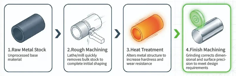
A typical precision part goes through three stages:
Rough machining (lathe / mill) → Heat treatment → Finish machining (grinder)
The lathe and mill remove most of the material and create the basic shape. Heat treatment improves hardness and wear resistance, while grinding completes the final dimensional accuracy and surface finish requirements.
Stage 1: Rough Machining (Lathe / Mill)
Raw stock is first roughed out on a lathe or mill, removing material until the part is close to its final dimensions. At this stage, the focus is shape and machining efficiency rather than final precision. A small amount of machining allowance is intentionally left for grinding because heat treatment can cause dimensional changes or slight distortion.
If a part is already finished before heat treatment, these changes can push the dimensions out of spec and affect the final accuracy.
Stage 2: Heat Treatment (Hardening)
Some high-precision parts go through heat treatment processes such as quenching, carburizing, or nitriding after rough machining to improve hardness, wear resistance, and service life.However, heat treatment can also change dimensions, distort the part shape, or affect the surface condition. The increased hardness can also make the material more difficult to machine, and ordinary cutting tools may struggle to maintain consistent accuracy.
That is why many hardened parts go through grinding afterward — to correct these changes and bring the part back to spec.
Stage 3: Finish Machining (Grinder)
Grinding uses the abrasive grains on a rotating grinding wheel as the cutting medium, making it suitable for hardened materials such as quenched steel and bearing steel.By controlling feed rate, wheel condition, and grinding parameters, the grinder corrects dimensional errors and achieves the tolerance, roundness, cylindricity, and surface roughness specified on the engineering drawing.
While turning and milling focus on removing material and shaping the part, grinding focuses on final precision control — ensuring stable and consistent quality before the part moves into assembly or operation.
Lathe vs. Mill vs. Grinder: Process at a Glance
| Lathe | Mill | Grinder | |
|---|---|---|---|
| Method | Rotating workpiece, single-point cutting | Rotating tool, milling to shape | Abrasive wheel, precision material removal |
| Best suited to | Rough machining, initial shaping | Rough machining, complex shapes | Finish machining, final precision |
| Hardened parts | Tool wears quickly | Tool wears quickly | Wheel handles it |
| Typical tolerance grade | IT8–IT7 | IT8–IT7 | IT8–IT5 |
| Typical Ra | 6.3μm ~ 0.4μm | 6.3μm ~ 0.8μm | 1.6μm ~ 0.1μm |
(Swipe left or right to view the full table.)
Note: data referenced from KeSu Group and Justway Wiki, based on ISO tolerance grade standards. Actual precision varies by machine model, wheel type, workpiece material, and process conditions.
Not Every Part Needs Grinding — But When Requirements Go Up, It Becomes the Deciding Factor
Plenty of parts look nearly finished right after turning or milling. But what actually determines how a part performs in service is often its contact condition, geometric accuracy, and surface quality after machining.
Once those requirements go beyond what standard cutting processes can reliably hold, grinding becomes a critical step in the manufacturing process. The two situations below are the most common reasons shops decide to bring grinding into their process.
Situation 1: The Part Needs Its Precision Restored After Heat Treatment
Processes such as quenching, carburizing, and nitriding improve a part's wear resistance and fatigue strength. However, the added hardness can also cause dimensional changes, meaning parts that were close to final size may need additional correction afterward.
As material hardness increases, conventional cutting tools experience faster wear, making it harder to maintain stable cutting performance and dimensional accuracy.
Grinding takes a different approach by removing material in small increments with an abrasive wheel. This allows hardened materials to be precisely corrected after heat treatment while maintaining the required dimensions and surface finish.
Typical examples include heat-treated precision shafts, finished gear surfaces, and machine components that need to withstand long-term wear.
Situation 2: The Part's Function Depends on Surface Quality
For some parts, performance depends on the quality of the contact surface — not just whether the dimensions match the drawing.
Sliding surfaces need to maintain proper clearance, sealing surfaces need consistent contact, and precision locating surfaces need accurate positioning after assembly. Surface waviness, machining marks, or local defects can affect movement, fit, and long-term reliability.
Grinding improves these functional surfaces by providing tighter control over surface roughness and geometric accuracy.
When a part needs more than just "dimensions on the drawing" — when it needs to perform consistently through assembly, operation, and years of service — grinding is often the final process that brings it to the required standard.
FAQ: Common Questions About Grinding Machines
Q1: Is a grinding machine the same as an angle grinder?
No. An angle grinder is a handheld tool mainly used for deburring, cutting, and surface cleanup. A grinding machine is a precision machine tool designed for controlled material removal and finish machining.
Although both use abrasive wheels, they serve completely different purposes. Grinding machines are built for applications where dimensional accuracy, surface finish, and repeatability matter.
Q2: How accurate is a grinding machine?
A grinding machine can typically achieve micron-level accuracy, depending on the machine design, wheel specification, workpiece material, and process conditions.
In precision applications, grinding is commonly used to improve dimensional accuracy, roundness, cylindricity, and surface finish after turning or heat treatment. The final result depends on the complete grinding setup rather than the machine alone.
Q3: Should I choose a cylindrical grinder or a centerless grinder?
The choice mainly depends on the part design and production requirements.
A cylindrical grinder is suitable for parts with center holes that require high form accuracy or complex profiles. A centerless grinder is better for high-volume production of simple cylindrical parts without center holes.
The key differences are workholding method, production volume, and application requirements.
Q4: What is the difference between an NC grinder and a CNC grinder?
An NC grinder is typically used for repeat production with fixed machining conditions and simpler operation requirements.
A CNC grinder provides programmable control, more flexible machining capability, and better support for complex parts or frequent changeovers.
For manufacturers handling multiple part types or tighter process requirements, CNC grinders offer greater flexibility and automation potential.
《Extended Reading: NC vs CNC: The Key Role of 2NC Cylindrical Grinders in Between》
Q5: What materials can be processed by a grinding machine?
Grinding machines can process a wide range of materials, including hardened steel, stainless steel, tool steel, carbide, ceramics, and other difficult-to-machine materials.
Because abrasive grains are harder than conventional cutting tools, grinding is especially effective for finishing hardened parts after heat treatment, where traditional machining becomes more challenging.
Need Help Choosing the Right Grinding Solution?
By now, you should have a clearer understanding of what a grinding machine is — from the basic grinding principle and key process steps to the differences between major grinder types and how grinding fits into a complete machining process.
If you are evaluating whether a cylindrical grinder or centerless grinder is the right choice for your application, TOPKING’s engineers can help assess your workpiece requirements, production volume, and precision targets to identify a suitable machine configuration.
TOPKING designs and manufactures NC and CNC cylindrical grinders and centerless grinders for a wide range of applications, from precision machining shops to automated production lines. Get in touch our team to discuss your grinding requirements.


TOPKING Technology
TOPKING Technology Co., Ltd., established in 2007, is a Taiwan-based manufacturer specializing in advanced precision grinding machines. With expertise in R&D, manufacturing, technical consulting, test grinding, training, and after-sales service, TOPKING provides high-quality cylindrical grinders, cross-slide cylindrical grinders, special-purpose grinding machines, and hydrostatic centerless grinders for industries such as automotive, aerospace, medical devices, and precision machinery worldwide.
Article Classification
Recent Articles
- What Is Centerless Grinding? Principles, Comparisons, and Process Selection
- What Is a Grinding Machine? Principles, Types, and Differences from Lathes and Milling Machines
- Overcoming Deformation in High-Aspect-Ratio Shafts: Practical Advantages of 30° Angular Grinding in Agricultural Output Shafts
- CNC Grinding Machines for Hydraulic Valve Spools
- Grinding Machine Explained: Principles, Types, and Applications