BLOG
- Home
- BLOG
- Cylindrical Grinder
- Overcoming Deformation in High-Aspect-Ratio Shafts: Practical Advantages of 30° Angular Grinding in Agricultural Output Shafts
Overcoming Deformation in High-Aspect-Ratio Shafts: Practical Advantages of 30° Angular Grinding in Agricultural Output Shafts

On precision parts production lines, gearbox output shafts for agricultural machinery are always a true test of machining expertise. To withstand high torque, these parts require extreme precision across outer diameters, stepped faces, spline bases, and fillets. Any deviation can lead to improper gear mesh, severely compromising the lifespan of the equipment. Let's look at the hidden manufacturing bottlenecks behind this application and see how a smart shift in machining logic can address them.
Manufacturing Integration on a Single Clamping: Flexibly Matching Varied Part Rigidity
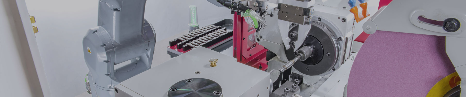
Beyond optimizing the distribution of cutting forces, the 30° angular wheelhead design of the X-2540A saves significant cycle time through its ability to complete multiple operations in a single clamping. In real-world production environments, we encounter drastically different part geometries, and a 30° angular grinder offers highly intelligent process solutions for each:
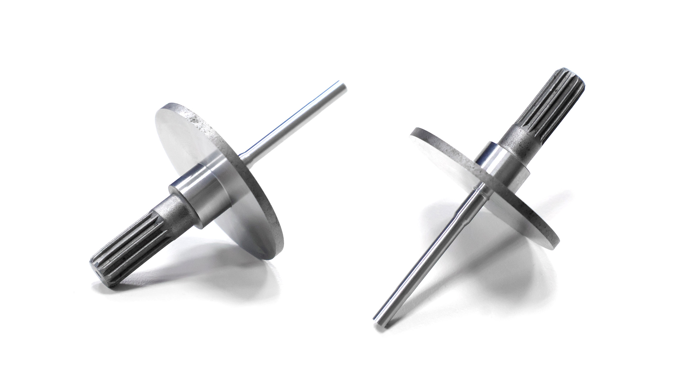
Case 1: High-Aspect-Ratio Workpieces with Large End Faces
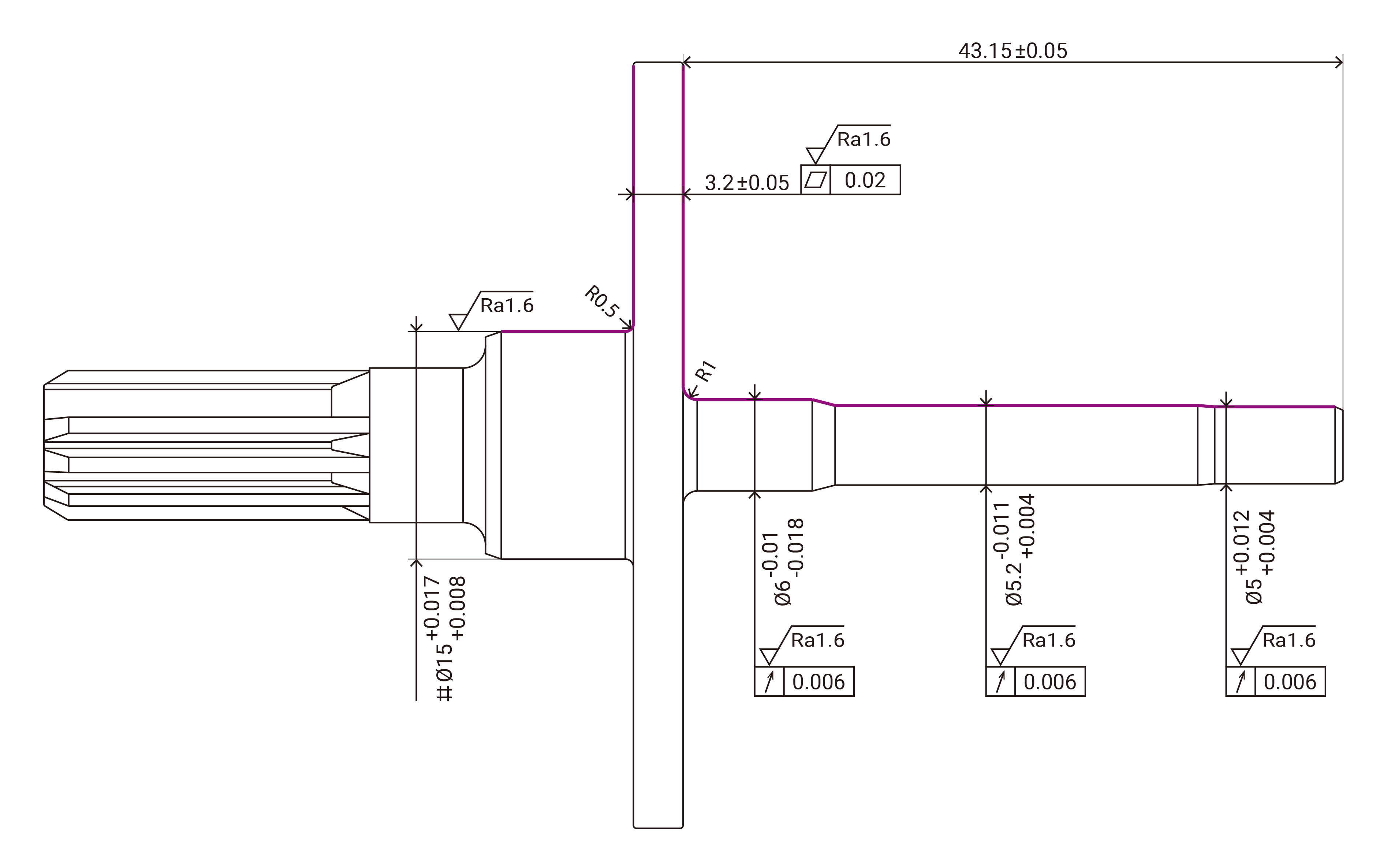
Looking at this output shaft blueprint, the right side features a slender shaft with a diameter of only 6 mm, while the center carries a large-diameter flange face. With such a massive gap in rigidity, attempting to rush the job by grinding the OD and the large face simultaneously forces a massive contact area. The resulting grinding stress can easily cause the slender shaft to deflect.
Therefore, the most reliable approach on the shop floor is a multi-step process within the same clamping: grind the OD first, then immediately switch to grinding the face and fillets. Although it isn't completed in a single synchronized stroke, the X-2540A's flexible 2-axis simultaneous feed eliminates the need to unload the part or use a secondary clamping setup. This eliminates hidden downtime from repetitive part handling and re-tooling. More importantly, the OD, large face, and the R1/R0.5 fillets are finished continuously using the exact same clamping datum point via CNC paths. This ensures that the flange's 0.02 mm parallelism and face squareness are locked in perfectly without any clamping tolerance stack-up.
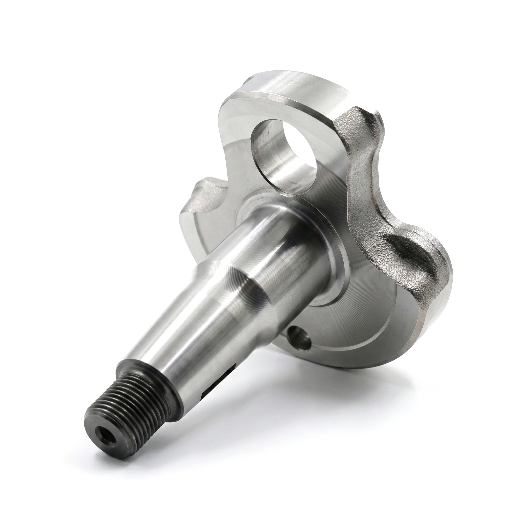
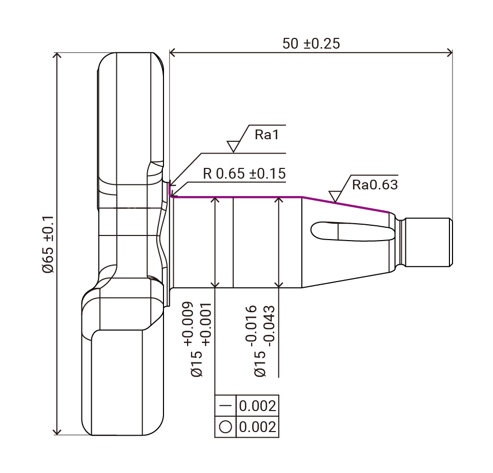
Case 2: Rigid, Asymmetric Workpieces
Now consider a crankshaft component for agricultural machinery or small power engines, such as this single-sided crankshaft (Crankshaft Half). While the left side also features a large-diameter 65 mm counterweight face, the main grinding diameter on the right reaches 15 mm. The overall structure has excellent rigidity, providing more than enough support to handle stable cutting forces.
However, the real challenge for this type of part lies in tight tolerance control. The print strictly demands a straightness and roundness of 0.002 mm, along with a precision 0.65 ± 0.15 mm fillet radius at the base.
For parts with adequate rigidity but unforgiving tolerances, the advantages of a 30° angular cylindrical grinder are fully unlocked. The wheel plunges at an angle, grinding the OD while simultaneously finishing the shoulder face and the R0.65 fillet in one synchronized motion. This single-stroke approach compresses a traditional two-step process into one. It not only slashes cycle times but also minimizes variations in cutting forces, allowing operators to consistently hit the 0.002 mm roundness and straightness specs—making it ideal for high-throughput, high-quality batch production.
- Flexible Cycle Time Management: Whether achieving one-stroke synchronized grinding like in Case 2, or opting for sequential grinding within a single clamping to protect slender part precision like in Case 1, the machine eliminates the wasted time associated with part transfer, switching machines, and recalibrating tailstock pressure. This keeps your cycle times highly optimized.
- Excellent Control Over Tolerance Stack-up: In the machining world, everyone knows that every time you release and re-clamp a part, you introduce variance. The greatest value of the X-2540A is its ability to secure the OD, multi-stepped faces, and precision fillets all within a single clamping, regardless of how challenging the geometry is. This eliminates human and mechanical tolerance stack-up between setups, giving the production line incredible process flexibility while locking in micron-level accuracy.
Why is a 0.006 mm Runout Tolerance So Hard to Maintain in Batch Testing?
In Case 1, the most troublesome area is the shaft section on the right. The diameters are only Ø6 mm, Ø5.2 mm, and Ø5 mm, yet the overhang length extends a whopping 43.15 mm. This high aspect ratio results in low structural rigidity, making the part highly susceptible to elastic deformation during machining.
Machining these parts presents a classic dilemma: to hold the workpiece securely and prevent center-hole slippage, operators often ramp up the hydraulic tailstock clamping pressure. However, doing so can easily bend a slender shaft that is only 5 to 6 mm in diameter.
With traditional straight plunge grinding, the grinding wheel engages the part with 100% of its width as soon as it advances. This large contact area generates massive radial thrust, pushing the slender shaft away—a phenomenon commonly known as part deflection.
This explains why so many factories find that while the first setup piece measures perfectly, the total runout across the three critical sections starts failing the strict 0.006 mm (6 μm) spec once batch production begins. Even resorting to a "grind one part, dress the wheel once" approach for the large face or the R1 mm/R0.5 mm fillets cannot counteract the physical forces causing the part to deflect and push away mid-process.
30° Angular Progressive Feed: Transforming Face Contact into a Light, Sequential Cut
To solve the deflection issues that push runout out of spec on slender shafts, the X-2540A Angular CNC Cylindrical Grinder introduces an ideal solution: a 30° angular wheelhead. This design fundamentally changes the feed logic compared to traditional straight plunge grinding. The 30° inclination angle evenly distributes grinding forces into both axial and radial components. Coupled with the precision interpolation of the X and Z axes, the wheel no longer plows straight into the side of the part; instead, it follows an angular path using a progressive feed.
Think of it as a highly controlled, sequential cut. The instantaneous contact area between the wheel and the slender shaft shrinks significantly, which naturally causes radial thrust to drop. Because the workpiece doesn't deflect or experience micro-bending during machining, the strict 0.006 mm runout tolerance can be reliably maintained during batch production. Supported by low-friction precision linear guides, ball screws, and a vibration-dampening Meehanite cast iron base, the slender shaft is provided an exceptionally stable machining environment.
Production Details Focused on Thermal Stability and Real-Time Compensation
Furthermore, both axes of the machine come standard with fully enclosed, high-resolution linear scales, sealing out coolant contamination and ensuring true closed-loop positioning. This can be paired with an optional in-process OD gauging system to measure parts in real time during the cycle, feeding data back to the control for automatic micron-level adjustments. Operators don't need to write complex G-code either; the built-in Graphical User Interface (GUI) guides them through the entire process setup visually.
If you are currently facing similar challenges with high-aspect-ratio parts on your floor, feel free to contact our engineering team for a comprehensive machining simulation and assessment!

TOPKING Technology
TOPKING Technology Co., Ltd., established in 2007, is a Taiwan-based manufacturer specializing in advanced precision grinding machines. With expertise in R&D, manufacturing, technical consulting, test grinding, training, and after-sales service, TOPKING provides high-quality cylindrical grinders, cross-slide cylindrical grinders, special-purpose grinding machines, and hydrostatic centerless grinders for industries such as automotive, aerospace, medical devices, and precision machinery worldwide.
Article Classification
Recent Articles
- Overcoming Deformation in High-Aspect-Ratio Shafts: Practical Advantages of 30° Angular Grinding in Agricultural Output Shafts
- Automated Match Grinding Solutions for Hydraulic Valve Components
- GRINDING MACHINE: essential for precision machining in manufacturing industry
- The Precision Revolution in Non-Round Grinding: Why Linear Motors are the Only Choice for Crankshaft and Camshaft Machining
- NC vs CNC: The Key Role of 2NC Cylindrical Grinders in Between