
BLOG
- Home
- BLOG
- Grinding Basics
- What Is Centerless Grinding? Principles, Comparisons, and Process Selection
What Is Centerless Grinding? Principles, Comparisons, and Process Selection
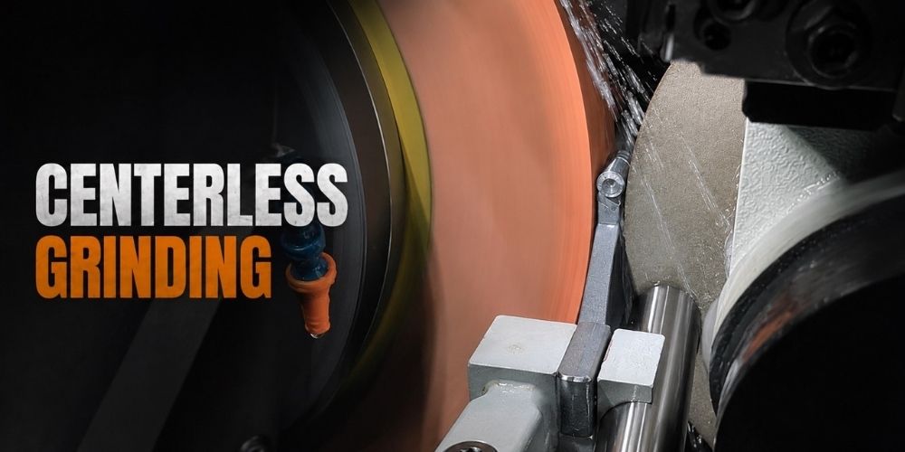
Centerless grinding is an outer-diameter (OD) grinding process for cylindrical parts that does not require a center hole, centers, chuck, or other workholding fixture. Instead, the workpiece is supported between three elements:the grinding wheel, the regulating wheel, and the work rest blade.
This article explains how centerless grinding works, the function of the three main components, the differences between through-feed and in-feed grinding, and how workpiece geometry and material affect process and machine selection.
What Is Centerless Grinding?
A centerless grinder is a precision machining equipment that uses a grinding wheel, an regulating wheel, and work rest blade to support the workpiece for grinding its outer diameter. During machining, the workpiece is positioned between the grinding wheel and the regulating wheel, and is rotated by the regulating wheel. The grinding wheel is responsible for removing material, so that the workpiece achieves the required dimensional accuracy, roundness, and surface roughness. The complete support system formed by these three components, combined with appropriate geometric positions and machining conditions, ensures a stable grinding process.
Centerless Grinding vs. Cylindrical Grinding
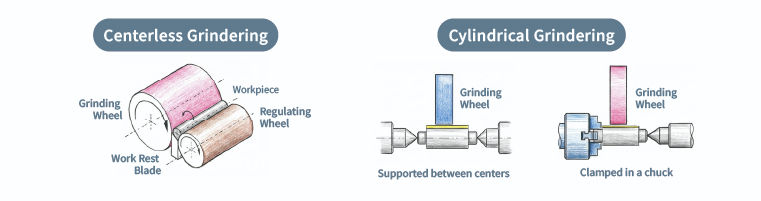
The key difference between centerless and cylindrical grinding is the way the workpiece is supported and rotated. Cylindrical grinding uses a fixed center axis, while centerless grinding supports and rotates the workpiece through the grinding wheel, regulating wheel, and work rest blade, without a center hole or individual clamping. This makes centerless grinding well suited to high-volume production.
〈Related Articles: Grinding Machine Explained:Principles, Types, and Applications〉
Comparison Table of Centerless Grinding and Cylindrical Grinding
| Item | Centerless Grinding | Cylindrical Grinding |
|---|---|---|
| Workholding | Grinding wheel, regulating wheel, and work rest blade | Centers or chuck |
| Working principle | Driven by the regulating wheel | Driven by the workhead |
| Center Hole | Not required | Usually required |
| Production | Continuous feeding; suitable for short cycle times | Individual loading and setup |
| Best suited for | High-volume, consistent OD grinding | Complex parts and varied production |
Why Is Centerless Grinding Used for High-Volume Production?
Continuous Through-Feed Grinding
In through-feed grinding, bar stock and pins pass continuously through the grinding zone one after another. The machine can keep grinding without stopping for individual loading and positioning, which helps reduce cycle times in high-volume production.
Stable Support for Slender Parts
Long, slender shafts can deflect under grinding forces when they are supported only at the ends. Centerless grinding supports the workpiece on the work rest blade throughout the grinding zone, reducing deflection and helping maintain consistent dimensional accuracy and roundness from part to part.
How Does a Centerless Grinder Hold Accuracy Without Clamping the Part?
A centerless grinder does not locate the workpiece with a chuck or centers, but the part is not free-floating. The grinding wheel, regulating wheel, and work rest blade establish its position and control its motion, with each component serving a specific function.
- Grinding Wheel:Removes material while the workpiece remains supported against the regulating wheel and work rest blade.
- Regulating Wheel:Rotates the workpiece by friction, controls rotational speed, and provides axial feed in through-feed grinding.
- Work Rest Blade:Supports the workpiece and maintains its position during grinding.
Together, the three components establish the grinding geometry. The workpiece can therefore rotate and move through the grinding zone without being clamped. Centerless grinding accuracy depends on the condition of the entire setup:regulating wheel wear, changes in blade height, inadequate wheel dressing, or incorrect parameters can result in roundness errors, dimensional drift, or other form and surface defects.
Grinding Wheel:Material Removal
The grinding wheel is the primary cutting tool in centerless grinding. Its abrasive grains remove stock, while the grinding force keeps the workpiece in contact with the work rest blade and regulating wheel.
Wheel speed affects the balance between surface finish and stock removal:
- Higher wheel speed:Generally supports finer surface finish. Each abrasive grain removes a smaller amount of material, which can produce a smoother surface and is commonly used for finishing.
- Lower wheel speed:Generally increases stock removal per grain. This can improve stock removal when more material must be removed.
In practice, wheel specification and grinding parameters are selected according to the workpiece material, roughing or finishing stage, stock removal, and required surface finish.
Regulating Wheel:Controls Rotation and Feed
The regulating wheel determines how the workpiece rotates and moves through the grinding zone. Its speed, tilt angle, and surface condition directly affect grinding stability and feed control.Stable contact between the regulating wheel and workpiece is essential for consistent rotation. Slippage, speed fluctuation, or excessive wheel wear can lead to variations in roundness, cylindricity, straightness, and surface finish.
For through-feed grinding, the regulating wheel tilt controls the axial movement of the workpiece through the grinding zone, while its speed influences the feed rate.
- Feed Speed:Determines how quickly the workpiece moves through the grinding zone.
- Feed Direction:Determines the direction of workpiece movement in through-feed grinding.
Work Rest Blade:Supports and Positions the Workpiece
The work rest blade supports the workpiece and resists grinding forces during machining. Its geometry and height are selected according to the workpiece and grinding method.
- Through-feed blade:Used for through-feed grinding.
- In-feed blade:Used for in-feed grinding.
Choosing the Right Work Rest Blade
A typical work rest blade has a top angle of about 30°. The blade geometry helps keep the workpiece seated against the blade during grinding and limits unwanted movement.
Blade material is selected based on contact conditions and wear resistance. Carbide, high-speed steel (HSS), and other wear-resistant materials are commonly used. The choice affects blade life and grinding stability and should match the workpiece material, required accuracy, and production volume.
Types of Centerless Grinding:Through-Feed and In-Feed
Centerless grinding is generally divided into through-feed and in-feed grinding based on how the workpiece is fed. In through-feed grinding, the workpiece passes completely through the grinding zone. In in-feed grinding, the workpiece remains in position while the grinding wheel feeds radially into the part.
The appropriate method depends on the workpiece geometry and the required grinding operation.
Through-Feed Grinding
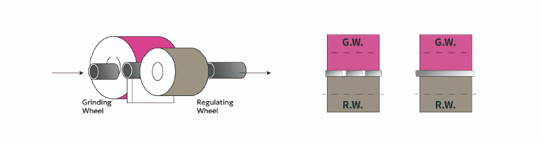
Through-feed grinding is the most common centerless grinding method for straight cylindrical parts. The regulating wheel is set at a slight angle to generate axial feed, carrying the workpiece through the grinding zone while the OD is ground.
Because the workpiece must travel through the full grinding zone, its OD must allow continuous axial movement. Shoulders, steps, and diameter changes therefore prevent through-feed grinding and are better suited to in-feed grinding. Typical through-feed parts include round bars, pins, rollers, and straight shafts.
Through-feed grinding is commonly used for parts produced repeatedly to the same specification, particularly in high-volume production.
In-Feed Grinding
In-feed grinding keeps the workpiece in one position while the grinding wheel feeds radially into the part. The workpiece rotates in place and does not move axially. Loading is typically from the top or front of the machine, depending on the setup.
In-feed grinding is used for parts that cannot pass through the grinding zone continuously, including stepped shafts, grooves, multiple diameters, and formed ODs. Typical applications include stepped shafts, special-feature shafts, bearing components, and precision parts where only a specific section requires grinding
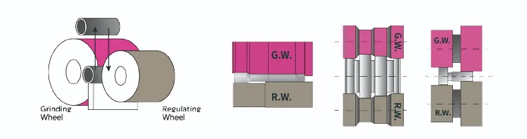
Through-Feed Grinding and In-Feed Grinding Methods
Centerless grinding is selected as through-feed or in-feed according to workpiece geometry and how the part must be presented to the grinding wheel. Through-feed is suited to straight cylindrical parts produced in volume, while in-feed is used for steps, grooves, multiple diameters, or localized grinding areas.
Through-Feed vs. In-Feed Grinding
| Item | Through-Feed Grinding | In-Feed Grinding |
|---|---|---|
| Workpiece Shape | Single cylindrical diameter; no shoulders or steps | Steps, grooves, multiple diameters, or formed OD |
| Processing Method | Workpiece travels axially through the grinding zone | Workpiece remains in position while the grinding wheel feeds radially |
| Typical Workpieces | Round bars, pins, rollers, motor shafts | Stepped shafts, special-feature shafts, bearing and multi-diameter parts |
| Processing Features | Continuous cycle; well suited to high-volume production | Grinds a defined section; accommodates discontinuous or complex OD features |
In short:
- Straight cylindrical shape, high volume → through-feed grinding
- Steps, grooves, or a specific section to grind → in-feed grinding
Some parts use both methods at different stages of the process. If you are unsure which method fits your part, provide the drawing, material, tolerances, and production volume so the grinding process can be evaluated against the part geometry and production requirements.
Selecting the Grinding Wheel, Regulating Wheel, and Blade
There is no single best combination of grinding wheel, regulating wheel, and blade. Selection depends on workpiece material and diameter, grinding method, required accuracy, stock removal, and production volume. The right combination supports process stability, wheel and blade life, and manageable setup and maintenance requirements.
Choosing the Grinding Wheel by Workpiece Material
Abrasive selection is based mainly on workpiece material, hardness, and tensile strength. Different abrasives have different cutting characteristics, and an unsuitable choice can lead to slow stock removal, excessive wheel wear, or inconsistent surface finish.
Abrasive Types and Characteristics
| Abrasive | Characteristics | Applicable Materials |
|---|---|---|
| Aluminum Oxide | Tough abrasive grain; suitable for higher-strength metals | Carbon steel, alloy steel, stainless steel, high-speed steel |
| Silicon Carbide | Hard, free-cutting abrasive; commonly used on brittle or non-ferrous materials | Cast iron, aluminum, copper, glass, ceramics, rubber, plastic |
Grit size, grade, and bond are selected together with the abrasive type, taking into account workpiece size, stock removal, grinding stage, and required surface finish.
How Does Regulating Wheel Setup Affect Grinding Stability?
The regulating wheel setup influences three main factors:
- Rotational speed:Controls the workpiece rotational speed and affects the time the part remains in the grinding zone.
- Feed rate:Affects cycle time and can influence surface finish.
- Workpiece path:Affects control of size, form, and the position of the grinding zone.
If wheel hardness, friction characteristics, or tilt angle are not matched to the grinding conditions, workpiece speed can fluctuate and affect roundness and dimensional stability.
How Does Blade Material Affects Grinding Quality?
Wear resistance is a primary consideration. The blade continuously supports the workpiece and absorbs grinding forces, so material wear directly affects blade life and grinding stability.
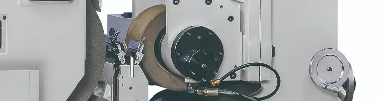
Blade Materials and Characteristics
| Material | Characteristics | Typical use |
|---|---|---|
| Carbide | High wear resistance; suitable for extended production | High-volume production, tight tolerances |
| High-Speed Steel (HSS) | Tougher and generally lower cost | Small diameters, non-ferrous parts |
| Close-grained cast iron, resin, or rubber-bonded materials | More compliant contact; lower risk of marking | Soft workpieces and parts with demanding surface-finish requirements |
(Mobile users can swipe the table left and right)
Blade selection balances workpiece material, diameter, weight, grinding method, and production volume. The most wear-resistant material is not necessarily the best choice for every application.
Which Parts Are Suitable for Centerless Grinding?
Centerless grinding is mainly used for cylindrical parts that require consistent OD quality across repeated production. Suitability depends on the workpiece geometry, production method, and required accuracy.
What Makes a Part a Good Fit?
Four conditions are useful when evaluating whether a part is suitable for centerless grinding:
- Straight, rotationally symmetric OD.CCenterless grinding is best suited to parts with a regular cylindrical OD, such as round bars, pins, rollers, and shaft sections. Parts with significant eccentricity, non-round profiles, or geometries that require conventional clamping may require another grinding method.
- Tight OD and roundness requirements. The three-point support establishes a defined grinding geometry, making centerless grinding suitable for controlled OD size, roundness, and surface finish.
- Slender parts prone to deflection. When part quantities are high and the specification remains consistent, continuous processing can improve throughput and reduce handling per part.
- High production volume. When quantities are high and the spec stays fixed, a steady cycle brings down the cost per par.
The more of these conditions apply, the stronger the case for evaluating centerless grinding. The final choice should still be based on part geometry, tolerances, material, production volume, and the required grinding cycle.
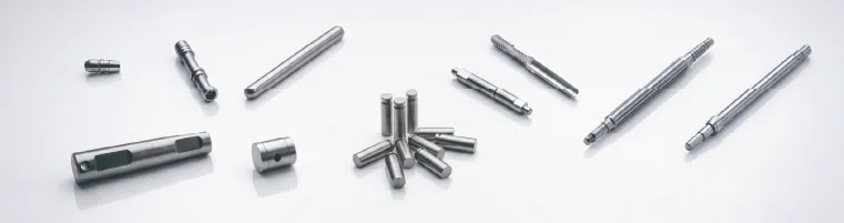
Where Centerless Grinding Is Used?
- Automotive Components:Common applications include shafts, pins, and transmission components where consistent OD dimensions are required across high-volume production. Because the workpiece is not individually clamped, the supporting geometry remains consistent throughout the run.
- Hydraulic Components:Valve spools, plungers, and similar precision parts often require controlled OD size, roundness, and surface finish. These characteristics affect sliding and sealing performance inside the valve body.
- Motor shafts and rollers:Typical through-feed applications. Parts move continuously through the grinding zone without stopping for individual positioning, making the process suitable for extended, high-volume production.
Advantages of Centerless Grinding
When evaluating a centerless grinder, manufacturers typically consider changeover time, process flexibility, material capability, labor requirements, and integration with automated production lines. Centerless grinding offers several advantages in these areas:
Continuous Grinding and Shorter Changeovers
Centerless grinders are suited to extended production runs. In through-feed grinding, parts enter the grinding zone at a controlled rate, reducing manual loading, unloading, and repeated handling. Once the setup is established, the process can support low-mix, high-volume production with relatively short changeovers.
Diverse Workpieces and Industrial Applications
Centerless grinding is widely used for OD finishing in automotive, bearing, hydraulic component, and precision hardware manufacturing. It can accommodate high-volume production of a single part number as well as different sizes and specifications when the machine is set up accordingly.
Works With a Wide Range of Materials
Centerless grinding can be applied to carbon steel, alloy steel, stainless steel, and other materials including cast iron, aluminum, glass, ceramics, rubber, carbide, and certain advanced alloys. Wheel abrasive selection should be matched to the workpiece material and required finish.
Ready for Automation
A centerless grinder can be integrated with CNC control, automatic loading and unloading, in-process gauging, and other automation equipment. This reduces manual handling and supports stable production on lines that run continuously.
Centerless Grinding FAQ
Q1:What materials are suitable for Centerless Grinding?
A:Centerless grinding can be used for many metals and selected non-metallic materials, including glass, ceramics, rubber, and plastics, provided the wheel abrasive and process conditions are appropriate. Because it is an OD grinding process, the workpiece must have a suitable cylindrical surface.
Silicon carbide is commonly selected for brittle materials and materials with lower tensile strength. Wheel selection also depends on material hardness, part size and geometry, stock removal, and the required accuracy and surface finish.
Q2:When is centerless grinding not the right choice?
A:Centerless grinding is generally not suitable for parts without a regular cylindrical OD. Parts with eccentric profiles, non-round cross-sections, features that require access from multiple directions, or several surfaces that must be finished in one clamping may be better suited to cylindrical or multi-process grinding.
A cylindrical grinder or multitasking machine provides more flexibility for clamping and accessing different features. The decision depends on part geometry, required accuracy, and the requirements of the overall process.
Q3:How do I choose between through-feed and in-feed Centerless Grinding?
A:Start with the workpiece geometry. Long parts with a single diameter and no steps are generally suited to through-feed grinding. Parts with steps, grooves, multiple diameters, or a localized area to be ground are generally suited to in-feed grinding.
Some parts fall between these categories, such as parts with a small diameter difference between the ends or a shallow groove. In those cases, the choice may depend on cycle time, dimensional tolerance, surface finish, and the specific machine setup.
Q4:What causes unstable quality in Centerless Grinding?
A:Common causes fall into three areas:the support geometry, the condition of the wheels and blade, and the grinding parameters. Out-of-round parts, chatter marks, dimensional drift, and surface scratches can each point to a different part of the process.
Three- or five-lobed roundness errors are often associated with workpiece center height. Chatter can be related to wheel imbalance, wheel specification, dressing, or unsuitable grinding conditions. Size drift and scratches may be related to regulating wheel condition, coolant, blade selection, or other process settings.
If redressing the wheel does not correct the problem, inspect the spindle, regulating wheel bearings, hydrostatic system, machine rigidity, and overall geometric accuracy. These areas can affect long-term process stability as the machine and components wear.
〈Related Articles:How to Choose the Right CNC Grinder:Match the Control System and Machine to Your Production Needs〉
Centerless Grinding Troubleshooting
| Symptom | Common Causes | Where to check |
|---|---|---|
| Poor Workpiece Roundness | Incorrect workpiece center height | Check blade height and workpiece center height |
| Chatter Marks on Surface | Grinding wheel imbalance or unsuitable wheel/process settings | Check wheel balance, dressing, and grinding parameters |
| Unstable Dimensions | Regulating wheel condition or changing grinding conditions | Check regulating wheel condition and process parameters |
| Surface Scratches | Insufficient coolant flow, residual chips, or unsuitable blade | Check coolant, part cleanliness, and blade configuration |
(Mobile users can swipe the table left and right)
Q5:How often should centerless grinding consumables be replaced?
A:There is no fixed replacement interval. Grinding wheel, regulating wheel, and blade life depends on workpiece material, production volume, stock removal, dressing practice, and grinding conditions.
The grinding wheel is dressed as it wears and replaced when dressing can no longer restore the required geometry or accuracy. Regulating wheel and blade replacement is based on wear, process stability, and whether the parts continue to meet quality requirements.
Maintenance intervals should be established from actual grinding conditions, production volume, and machine operating hours rather than from a fixed calendar schedule.
Q6:What costs should be considered before buying a centerless grinder?
A:Purchase price is only one part of the total cost. Operating costs include grinding and regulating wheels, blades, loading and unloading automation, floor space, first-article setup and parameter adjustment, coolant and related systems, and the labor required to operate and maintain the machine.
Centerless grinding typically delivers the greatest value in high-volume, continuous production. Machine evaluation should therefore start with the part, required accuracy, production volume, grinding method, and planned level of automation.
TOPKING H Series Centerless Grinders | Precision and Stability
For work with tight roundness and surface finish requirements, the TOPKING H series is worth evaluating. Hydrostatic spindle and guideways keep friction and wear down during continuous operation. A high-rigidity Meehanite cast iron structure and a minimum feed increment of 0.0005 mm support roundness and surface finish on precision work. The series is available with NC or CNC control in several sizes, covering workpiece diameters from Ø1 to Ø45 mm and Ø2 to Ø75 mm depending on model, for precision work, extended production, and automated lines.
〈Product Recommendation:Centerless Grinding Machines〉
Conclusion
Centerless grinding is particularly effective for cylindrical OD applications where continuous feeding, repeatable support, and consistent part quality are required. Process results depend on matching the grinding wheel, regulating wheel, and work rest blade to the application and setting the machine accurately.
After the grinding method and process conditions are defined, machine selection should consider workpiece size, grinding method, control system, structural rigidity, and automation requirements.
If you are evaluating centerless grinding for your production line, provide the workpiece drawing, material, dimensional tolerances, and production volume. Contact TOPKING, and our specialists will help analyze your needs.


TOPKING Technology
TOPKING Technology Co., Ltd., established in 2007, is a Taiwan-based manufacturer specializing in advanced precision grinding machines. With expertise in R&D, manufacturing, technical consulting, test grinding, training, and after-sales service, TOPKING provides high-quality cylindrical grinders, cross-slide cylindrical grinders, special-purpose grinding machines, and hydrostatic centerless grinders for industries such as automotive, aerospace, medical devices, and precision machinery worldwide.
Article Classification
Recent Articles
- What Is Centerless Grinding? Principles, Comparisons, and Process Selection
- What Is a Grinding Machine? Principles, Types, and Differences from Lathes and Milling Machines
- Overcoming Deformation in High-Aspect-Ratio Shafts: Practical Advantages of 30° Angular Grinding in Agricultural Output Shafts
- CNC Grinding Machines for Hydraulic Valve Spools
- Grinding Machine Explained: Principles, Types, and Applications