
BLOG
- Home
- BLOG
- Grinding Basics
- The Precision Revolution in Non-Round Grinding: Why Linear Motors are the Only Choice for Crankshaft and Camshaft Machining
The Precision Revolution in Non-Round Grinding: Why Linear Motors are the Only Choice for Crankshaft and Camshaft Machining
What Is a CAM Grinder? CAM Grinding Principles and Selection Guide
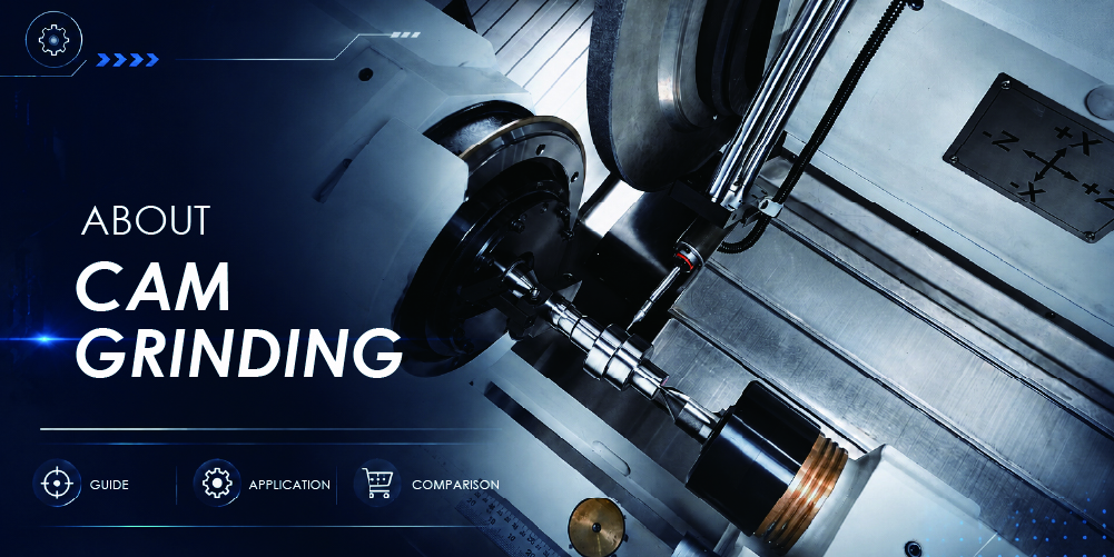
A CAM grinder is a CNC grinding machine designed for machining workpieces with non-circular profiles, such as camshafts, crankshafts, eccentric shafts, and non-circular punches. Unlike conventional cylindrical grinding, which is mainly used for round outer diameters, CAM grinding requires the grinding wheel position to continuously adjust according to the changing profile of the rotating workpiece.
In precision manufacturing, selecting the right grinding machine depends on the geometry of the workpiece and the required machining performance. For components with standard cylindrical surfaces, a cylindrical grinder can effectively control dimensional accuracy, roundness, and surface finish. However, when a workpiece contains eccentric features, special curves, or non-circular contours, a CAM grinder provides the profile control capability required for these applications.
CAM grinders are commonly used for precision components including camshafts, crankshafts, eccentric shafts, and non-circular punches. These parts require more than dimensional control. The grinding process must also maintain profile accuracy, positional relationships, and the functional movement characteristics of the finished component.
This article explains what a CAM grinder is, how CAM grinding works, common applications, and how to select the right CNC grinding machine for non-circular machining requirements.
〈Related product:CNC CAM grinding | X-CAM series〉
Cylindrical Grinder vs. CAM Grinder: Understanding the Difference
In grinding applications, the machining method is determined by the geometry of the workpiece. A cylindrical grinder is mainly used for round components such as shafts, sleeves, rollers, and hydraulic components. The main focus is controlling outer, diameter accuracy, roundness, cylindricity, surface finish.
A CAM grinder, also known as a non-cylindrical grinding machine, is designed for workpieces where the distance between the rotation center and the grinding surface changes during rotation. During non-circular grinding, the grinding wheel must continuously compensate according to the programmed workpiece profile. For example:
- A camshaft requires accurate control of the cam lift curve.
- An eccentric shaft requires precise control of eccentricity and angular position.
- A crankshaft requires accurate positioning between main journals and crank pins.
Therefore, a cylindrical grinder and a CAM grinder are not replacement options for each other. The correct choice depends on the workpiece geometry, production requirements, and required profile accuracy.
How Does CAM Grinding Work? X-axis and C-axis Synchronized Control
The core technology of a CAM grinder is the synchronized motion control between the X-axis and C-axis.
- C-axis:Controls the rotation angle of the workpiece.
- X-axis:Controls the grinding wheel position and feed movement.
Before machining, the CNC control system uses the workpiece profile data to generate the grinding path. During operation, as the C-axis rotates the workpiece, the control system calculates the corresponding profile position and adjusts the X-axis movement to keep the grinding wheel following the designed contour. In simple terms, CAM grinding does not remove material based on a fixed diameter. Instead, the grinding wheel position is continuously compensated according to the profile coordinates at each rotation angle.
For example:
- During cam grinding, the grinding wheel follows the cam lift curve to maintain the correct profile throughout the rotation cycle.
- During eccentric shaft grinding, the machine controls the eccentric amount and rotational phase position to achieve the required geometry.
This synchronized X-axis and C-axis interpolation capability is the foundation of accurate non-circular grinding.
CAM Grinder vs. Conventional Cylindrical Grinder
| Comparison Factor | CAM Grinder | Conventional Cylindrical Grinder |
|---|---|---|
| Applicable Workpieces | Non-circular components such as camshafts, crankshafts, eccentric shafts, and non-circular punches | Round components such as shafts, sleeves, rollers, and cylindrical parts |
| Profile Control Method | X-axis and C-axis synchronized control for non-circular contour compensation | Mainly optimized for cylindrical outer diameter grinding |
| Drive System | High-response linear motor drive for profile compensation motion | Ball screw drive commonly used for conventional grinding applications |
| Programming Requirements | Requires CAD/CAM contour path planning for complex profiles (such as TWCAD) | Standard CNC programming is sufficient for cylindrical grinding |
| Long-term Accuracy Stability | Reduced impact from mechanical transmission backlash and wear | Accuracy may require adjustment as mechanical components wear over time |
| Production Impact | Faster changeover, consistent production quality, and reduced long-term maintenance requirements | 仰More dependent on operator experience and less suitable for complex profile mass production |
(Swipe left or right to view the full table.)
Why Does CAM Grinding Require High-Speed Synchronized Control?
During CAM grinding, the grinding wheel position must continuously change according to the workpiece rotation angle. Therefore, the machine requires not only high positioning accuracy but also strong dynamic response. When the workpiece profile changes rapidly within a short rotation range, the X-axis must complete precise micro-adjustments at high speed. If the drive system has mechanical backlash or delayed response, the actual grinding wheel position may deviate from the programmed contour, affecting the final profile accuracy.
For this reason, high-precision CAM grinders often use high-response drive systems to improve profile tracking performance during high-speed interpolation. Linear motors reduce the influence of mechanical transmission components and are suitable for non-circular grinding applications requiring frequent compensation movements.Different machines may adopt different drive configurations depending on the application. However, fast response and low following error are key design considerations for precision non-circular grinding.
What Is the Relationship Between a CAM Grinder and a Cam Grinding Machine?
In search markets, cam grinding machine is a commonly used term. However, a cam grinding machine is actually one application category within the broader field of CAM grinding. The relationship can be summarized as follows:
- CAM grinder / Non-cylindrical grinding machine: Covers a wide range of non-circular profile grinding applications,including cam grinding, crankshaft grinding, eccentric shaft grinding, and special profile grinding.
- Cam grinding machine: Mainly focuses on camshaft machining. Requires precise control of cam lift curves, working angles, and profile accuracy.
A CAM grinder provides broader non-circular grinding capability for different industries and complex profile components.
Common applications include:Camshafts, Crankshafts, Eccentric shafts, Non-circular punches, Precision mold components. The common characteristic of these components is that their geometry cannot be defined by a simple cylindrical diameter. The machining process must control the overall profile, positional relationship, and functional movement characteristics. For example:
- A camshaft controls valve movement through its lift profile.
- A crankshaft requires precise positioning between main journals and crank pins.
- An eccentric shaft requires accurate control of eccentricity and phase relationships.
〈Related Articles:GRINDING MACHINE: essential for precision machining in manufacturing industry〉
What Workpieces Can a CAM Grinder Machine?
A CAM grinder is designed for precision grinding of workpieces with non-circular profiles, eccentric geometries, or complex contours. Unlike conventional cylindrical grinding, where the focus is on diameter and surface finish, CAM grinding must also maintain contour accuracy, eccentricity, and the geometric relationship between multiple features. Typical applications include camshafts, crankshafts, eccentric shafts, non-circular punches, and precision tooling components.
Camshafts: Precision Motion Profile Components
Camshafts are widely used in automotive valve trains, textile machinery, and automated mechanical systems. Their primary function is to control the timing, lift, and motion of moving components through a precisely designed cam profile.In automotive engines, the cam profile directly affects valve timing, valve lift, fuel efficiency, and engine performance. In high-speed textile machinery, it determines motion accuracy and operating stability.
Unlike a simple cylindrical surface, a cam profile consists of multiple functional sections, including the base circle, lift, dwell, and return. Because the profile must generate complex motion throughout each rotation, camshaft grinding focuses not only on dimensional accuracy but also on maintaining the designed contour and motion characteristics.Key quality requirements for camshaft grinding include lift profile accuracy, contour accuracy, phase relationship, working angle, and surface finish. Since profile errors directly affect machine performance, camshaft grinding typically requires the contour control capability of a CNC CAM grinder.
.jpg)
Crankshafts: Machining Both Round and Eccentric Journals
Crankshafts are widely used in automotive engines, agricultural equipment, air compressors, and other power transmission systems. Their primary function is to convert the reciprocating motion of pistons into rotational torque.
One of the main challenges in crankshaft grinding is that a single workpiece contains both main journals with a true cylindrical profile and crank pins with eccentric geometry. These features must maintain precise positional relationships throughout the grinding process.
In addition to dimensional accuracy, crankshaft grinding requires tight control of eccentricity, roundness, cylindricity, journal concentricity, and phase angle. Even small deviations can affect rotational balance, power transmission, and component life.While dedicated crankshaft grinders are commonly used for high-volume production, CAM grinders are well suited for prototype work, special crankshafts, and applications requiring flexible non-circular contour grinding.
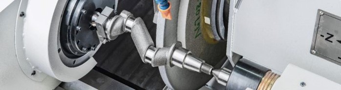
Eccentric Shafts: Critical Components in Precision Motion Systems
Eccentric shafts are commonly used in RV reducers, robotic joints, pumps, air compressors, and other precision transmission systems. As industrial automation and robotics continue to expand, they have become key components for achieving high torque and low-backlash motion. Unlike conventional shafts, the rotational center of an eccentric shaft does not coincide with its machined profile. The grinding process must accurately control both eccentricity and angular position. Components with multiple eccentric sections also require precise phase relationships between journals to ensure proper assembly and motion.
For this reason, eccentric shaft grinding requires more than dimensional control. It must also maintain eccentricity, roundness, geometric accuracy, and the positional relationship between multiple shaft sections. For example, eccentric shafts used in RV reducers drive cycloidal motion through precision eccentric geometry. Any profile deviation may affect positioning accuracy, transmission efficiency, and backlash performance. These demanding requirements make eccentric shaft grinding one of the most challenging applications for CAM grinders.
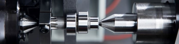
Non-Circular Punches and Precision Tooling Components
Non-circular punches and precision tooling components are widely used in precision stamping, cold forging, and specialized forming applications. Depending on the manufacturing process, these parts may feature hexagonal, elliptical, polygonal, or custom profile geometries, making them typical applications for non-circular grinding. For these components, machining accuracy involves more than controlling dimensions. Maintaining contour accuracy, tooling fit, and long-term dimensional stability is equally important. Even small profile deviations can affect part quality, dimensional consistency, and tool life.
CNC CAM grinding provides a repeatable process for controlling profile accuracy, geometric precision, and surface finish while reducing the variability associated with manual finishing.
.jpg)
CAM Grinding Limitations to Consider Before Machining
Although CAM grinders can machine a wide range of non-circular profiles, the final result still depends on the workpiece design, grinding wheel geometry, and contour complexity. Before production, it is important to confirm that the part is suitable for the grinding process.
- Concave Radius Limitation:The grinding wheel determines the minimum concave radius that can be machined. If a concave feature has a smaller radius than the grinding wheel, the wheel cannot fully access the profile. The workpiece design should therefore be evaluated together with the selected grinding wheel geometry.
- Sharp Concave Profiles:Because a grinding wheel has a fixed radius, it cannot produce perfectly sharp concave features. Parts with deep recesses or extremely small internal concave profiles should include an appropriate corner radius to ensure the grinding wheel can follow the intended contour.
- Dynamic Compensation Capability:During non-circular grinding, the grinding wheel must continuously follow changes in the workpiece profile. If the contour changes rapidly over a very small angular range, the machine must provide sufficient dynamic response to maintain accurate contour tracking. Before machining complex profiles, CAD/CAM simulation is typically used to verify the grinding path and ensure the grinding wheel can follow the designed contour, helping reduce setup time and trial machining.
A Wide Range of Non-Circular Profiles Can Be Ground

Non-Circular Profiles with Machining Limitations

Key Design Features of the X-CAM Series CAM Grinder
The quality of non-circular grinding depends on more than the CNC control system. Machine structure, drive technology, and long-term mechanical stability all influence machining performance. When grinding workpieces with rapidly changing contours or eccentric geometries, the machine must maintain high-speed, high-frequency position compensation throughout the grinding cycle.For this reason, the design of a CAM grinder focuses on drive response, machine rigidity, and long-term accuracy retention.
The TOPKING X-CAM Series is designed for camshaft, crankshaft, eccentric shaft, and other non-circular grinding applications. It combines a linear motor drive, cross-slide structure, and high-speed synchronized motion control to improve contour tracking accuracy and machining stability.
Why Does a CAM Grinder Use a Linear Motor?
During non-circular grinding, the X-axis must continuously compensate for changes in the workpiece profile as the C-axis rotates. The response speed and positioning stability of the drive system therefore have a direct impact on contour accuracy. Conventional ball screws transmit motion through mechanical contact. Over time, repeated high-speed reciprocating movement can introduce backlash and wear, gradually affecting positioning accuracy. A linear motor generates motion directly through electromagnetic force, eliminating intermediate transmission components. This provides several advantages:
- Zero mechanical backlash
- High acceleration and rapid response
- Well suited for high-frequency contour compensation
For CAM grinding applications that require continuous wheel position adjustment, a linear motor helps maintain stable contour tracking performance. The X-axis of the X-CAM Series is driven by a linear motor with a maximum rapid traverse speed of 15,000 mm/min, providing fast response during high-speed compensation.
(1).jpg)
How Does a Cross-Slide Design Improve Grinding Stability?
In addition to the drive system, machine structure plays an important role in grinding accuracy. Many conventional grinding machines use separate X-axis and Z-axis assemblies. The X-CAM Series adopts an integrated X/Z cross-slide design, where both axes are built on the same structural reference. Compared with a conventional separate-axis layout, the cross-slide design shortens the force transmission path and reduces moving mass, helping minimize structural deflection and accumulated positioning errors during high-speed interpolation.
For CAM grinding, this is particularly important because the grinding wheel position must accurately follow the contour coordinates calculated by the CNC system as the X-axis and C-axis move simultaneously. Any geometric drift in the machine structure over time may reduce contour consistency. Maintaining stable axis geometry is therefore essential for long-term machining accuracy.
Cross-Slide Design Verified to VDI 3441 Accuracy Standards
X-Series,Every X-Series machine is tested in accordance with VDI 3441 positioning accuracy standards. Measured results include:
- X-axis positioning accuracy (Pa): approximately 0.348 μm
- Z-axis repeatability (Ps max): 1.554 μm
- X-axis reversal error (U max): only 0.398 μm, indicating excellent positioning consistency during bidirectional motion
.png)
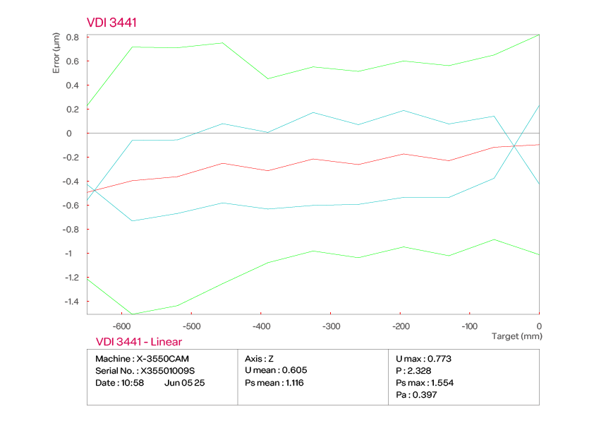
Combined with the X-axis linear motor, C-axis direct-drive motor, and circular optical encoder, the system provides real-time contour compensation during grinding and delivers roundness within3μm, depending on the workpiece and grinding conditions.
Cross-Slide Design vs. Conventional Separate X/Z Design
| Feature | Cross-Slide Design | Conventional Separate X/Z Design |
|---|---|---|
| Structure | Integrated X and Z axes on a single cross-slide | Separate X and Z axis assemblies |
| Structural Rigidity | Common structural reference improves stability during synchronized motion | Independent structures designed for a wider range of machining applications |
| Interpolation Performance | Optimized for high-speed X/C-axis synchronized interpolation | Suitable for conventional cylindrical and general-purpose grinding |
| Dynamic Response | Lower moving mass improves high-frequency compensation | Dynamic performance depends on machine configuration |
| Contour Tracking Accuracy | Helps reduce following error during high-speed contour grinding | Depends on the drive system and control configuration |
| Typical Applications | CAM grinding, eccentric shafts, and non-circular profiles | Standard cylindrical grinding, stepped shafts, and general grinding applications |
(Swipe left or right to view the full table.)
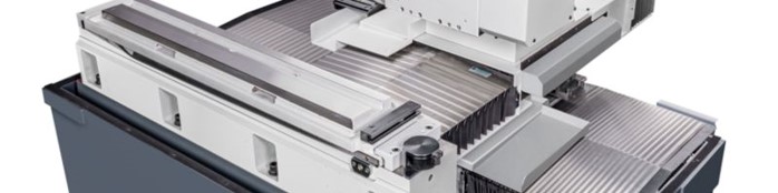
X-CAM Series Performance Verification: Eccentric Shaft Grinding
To evaluate the grinding performance of the X-CAM Series on eccentric components, TOPKING conducted grinding tests using an eccentric shaft workpiece.
The measured results were as follows:
- Roundness: 1.1 μm, 1.2 μm, 1.1 μm across multiple sections
- Cylindricity: 1.5 μm
- Diameter control: maintained between 38.1007 mm and 38.1019 mm
- Eccentricity: maintained roundness better than 3μm on a workpiece with 4.7645 mm eccentricity.
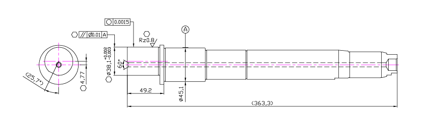
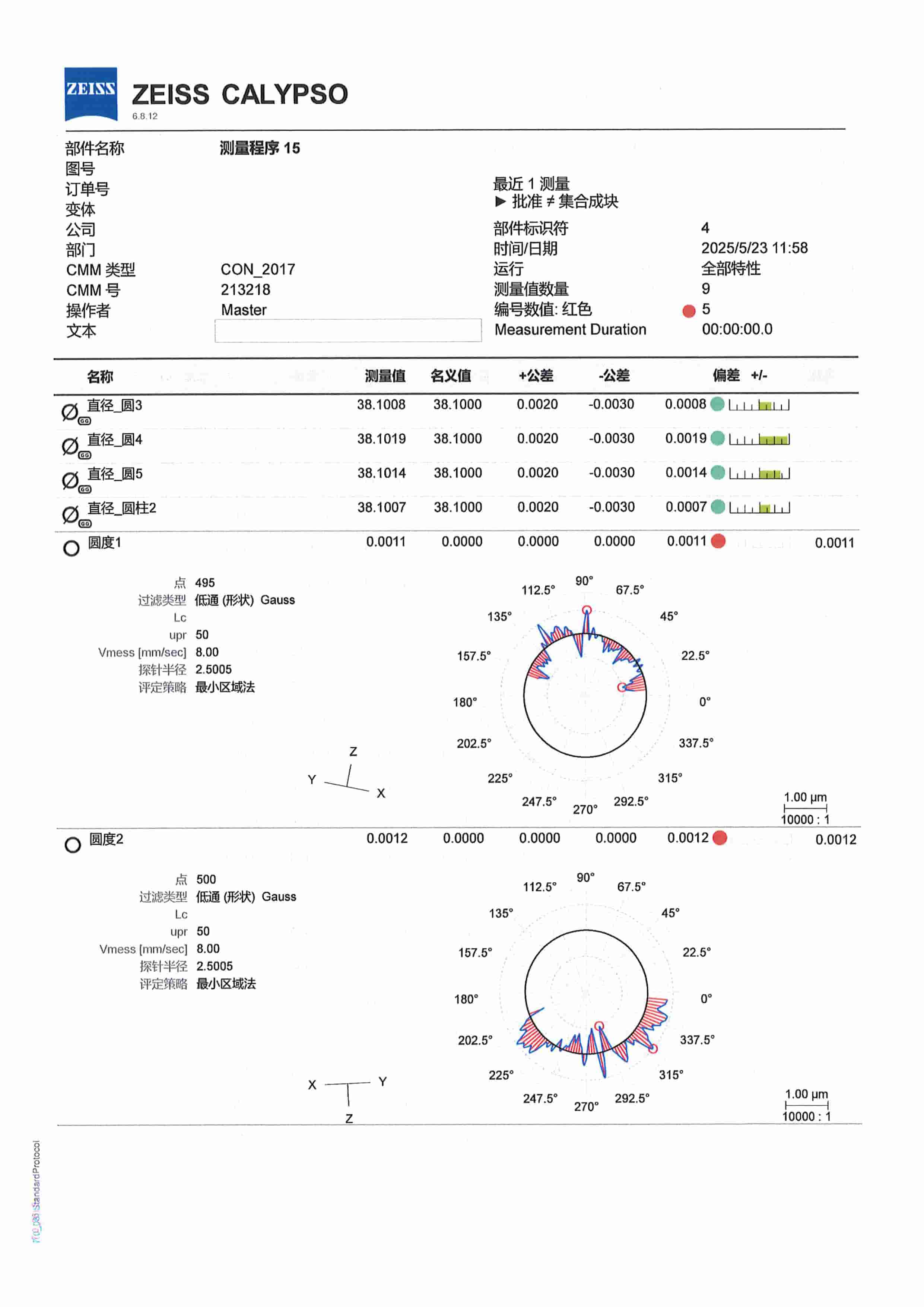
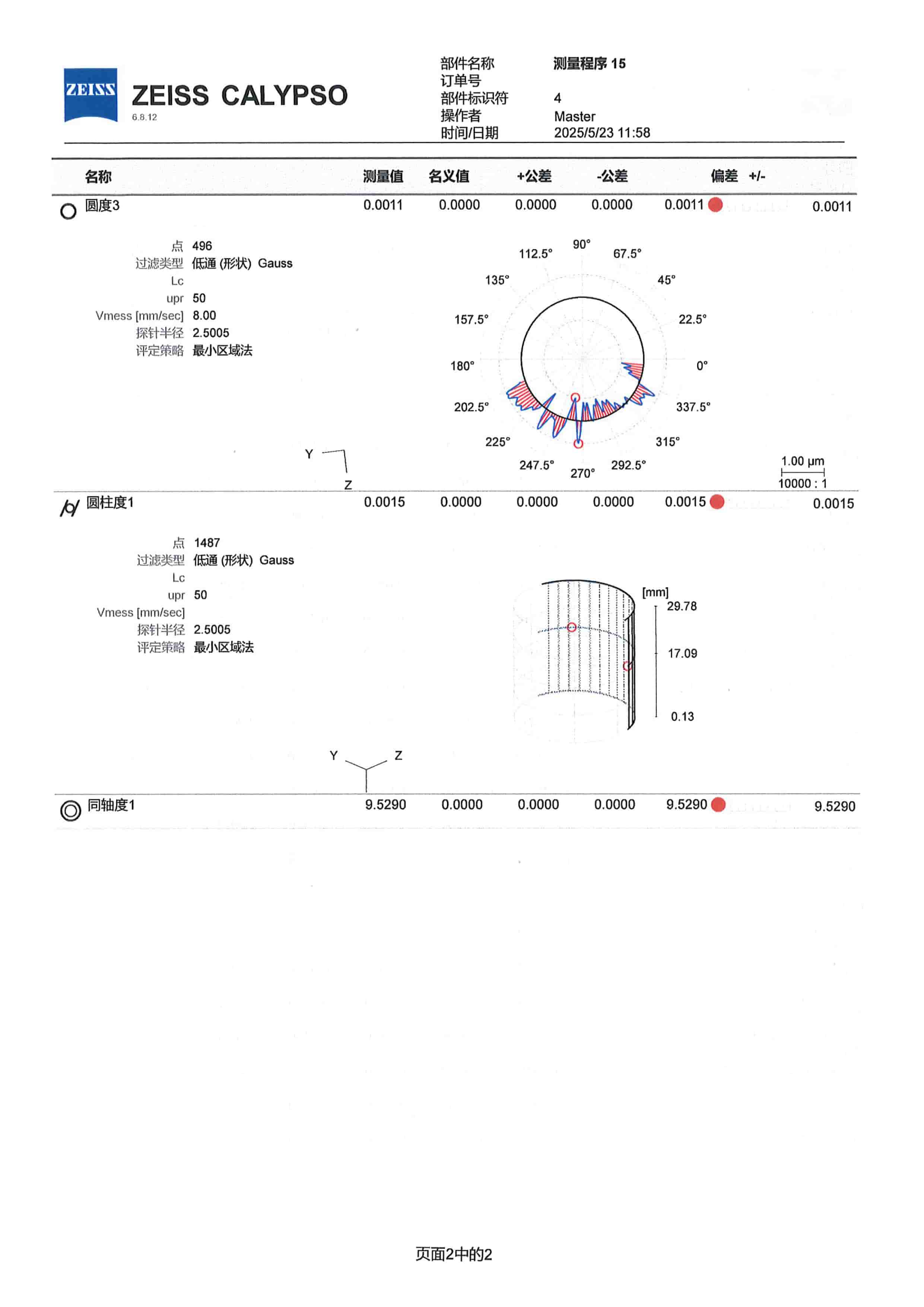
These test results demonstrate that the X-CAM Series maintains stable dimensional control and geometric accuracy even when grinding eccentric workpieces. For manufacturers producing precision components in volume, application test results like these provide a more practical indication of machine capability than specifications alone.
How to Choose the Right CAM Grinder
Selecting the right CAM grinder involves more than confirming whether it can machine your workpiece. You should also evaluate the complexity of the profile, production volume, programming requirements, and the machine's ability to maintain accuracy over long production runs. The following factors are typically the most important when selecting a CNC CAM grinding machine.
Workpiece Geometry and Grinding Requirements
Start by identifying the type of non-circular profile you need to machine. Different applications place different demands on interpolation performance, axis configuration, and software support.
- Camshafts:Focus on lift curve accuracy and profile precision.
- Crankshafts::Require precise control of eccentric journals and their positional relationships.
- Eccentric shafts:Require accurate eccentricity control and phase-angle positioning.
Choosing a machine designed for your specific application helps improve machining accuracy while reducing setup complexity.
Production Volume and Changeover Efficiency
If your shop frequently switches between different workpieces, programming efficiency and changeover time become critical. For repeat jobs, stored CNC programs and profile data allow previously qualified parts to be recalled quickly, reducing setup time and improving production efficiency.
Machines with integrated CAD/CAM support also simplify profile management and shorten the transition between different products.
Long-Term Accuracy Stability
CAM grinding is typically used for high-precision components, making long-term machine stability just as important as its initial accuracy. When evaluating a machine, consider factors such as:
- Drive system wear
- Positioning stability
- Machine rigidity
- Maintenance requirements
For manufacturers running continuous production, the ability to maintain consistent machining accuracy over time is often more valuable than achieving the highest specification on day one.
CAM Grinder FAQ
Q1:What roundness can a CAM grinder achieve?
A well-designed CAM grinder can maintain roundness within3μm epending on the workpiece, grinding conditions, and process setup.
Based on testing performed on the TOPKING X-CAM Series, eccentric shaft samples achieved multi-section roundness values of1.1~1.2 μm.
Technical Note: High-speed synchronization between the X-axis linear motor, C-axis direct-drive motor, and circular optical scale enables real-time profile compensation while minimizing the effects of backlash and response delay.
〈Related Articles:Hydrostatic Technology: The Key to Stable Centerless Grinding〉
Q2:How long does it take to change over to a different workpiece?
Previously programmed workpieces can typically be changed over in less than one hour.
Technical Note: Simple eccentric parts can be edited directly through the machine's conversational interface. More complex profiles, such as camshafts and non-circular punches, are generated using CAD/CAM software. Once the profile is created, it can be reused for future production with minimal setup time.
Q3:How is a cam lift profile converted into a grinding path?
Using TWCAD, cam lift data can be converted into a complete contour model and grinding path before machining begins.
Technical Note: The software imports lift data, generates the profile geometry, simulates synchronized X- and C-axis motion, and verifies contour continuity before production.
Q4:Why do CAM grinders use linear motors?
Non-circular grinding requires the grinding wheel to make continuous, high-speed position corrections as the workpiece rotates. Traditional ball screw systems can introduce backlash and response delay during rapid interpolation, affecting profile accuracy.
Technical Note: Linear motors eliminate mechanical backlash and provide high acceleration, allowing the X-axis to reach speeds of up to 15,000 mm/min while maintaining accurate contour tracking.
〈Related Articles:Overcoming Deformation in High-Aspect-Ratio Shafts: Practical Advantages of 30° Angular Grinding in Agricultural Output Shafts〉
Q5:Why is a cross-slide design important for CAM grinding?
A cross-slide structure helps maintain a stable geometric relationship between the X- and Z-axes throughout the machine's service life.
Technical Note: Because both axes are integrated into the same structural module, interpolation accuracy remains more consistent during long-term operation, reducing geometric drift during high-speed contour grinding.
Q6:What support does TOPKING provide after machine installation?
TOPKING provides comprehensive technical support throughout the machine's operating life, including:
- Machine installation and operator training
- Remote technical support for troubleshooting
- One-year warranty on major components
- Continued spare parts supply and technical assistance after the warranty period
Looking for the right CAM grinder for your application?
Choosing a CAM grinder is not about selecting the machine with the most features—it's about selecting the machine that best matches your workpiece geometry, production requirements, and precision goals.
The TOPKING X-CAM Series is designed for grinding camshafts, crankshafts, eccentric shafts, and other non-circular components. Combining high-speed synchronized control, linear motor technology, and a rigid cross-slide structure, it provides stable and repeatable performance for demanding CAM grinding applications.
Our application engineers can review your workpiece drawing, evaluate the grinding process, and recommend the right machine configuration for your production requirements.

TOPKING Technology
TOPKING Technology Co., Ltd., established in 2007, is a Taiwan-based manufacturer specializing in advanced precision grinding machines. With expertise in R&D, manufacturing, technical consulting, test grinding, training, and after-sales service, TOPKING provides high-quality cylindrical grinders, cross-slide cylindrical grinders, special-purpose grinding machines, and hydrostatic centerless grinders for industries such as automotive, aerospace, medical devices, and precision machinery worldwide.
Article Classification
Recent Articles
- What Is Centerless Grinding? Principles, Comparisons, and Process Selection
- What Is a Grinding Machine? Principles, Types, and Differences from Lathes and Milling Machines
- Overcoming Deformation in High-Aspect-Ratio Shafts: Practical Advantages of 30° Angular Grinding in Agricultural Output Shafts
- CNC Grinding Machines for Hydraulic Valve Spools
- Grinding Machine Explained: Principles, Types, and Applications