BLOG
- Home
- BLOG
- Cylindrical Grinder
- The Precision Revolution in Non-Round Grinding: Why Linear Motors are the Only Choice for Crankshaft and Camshaft Machining
The Precision Revolution in Non-Round Grinding: Why Linear Motors are the Only Choice for Crankshaft and Camshaft Machining
March 05,2026

X-Series CAM: Guaranteeing 3 μm Roundness in Non-Round Grinding via "Zero Backlash" Technology
A New Standard for Precision Manufacturing
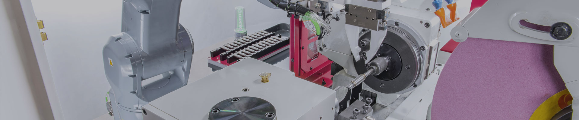
In precision manufacturing, traditional cylindrical grinding techniques struggle to meet the stringent accuracy and efficiency requirements of complex workpieces like crankshafts, camshafts, or asymmetrical punches. The X-Series CAM grinding machines are specifically engineered for "non-round profiles" and "eccentric" machining. By utilizing linear motor drives and a cross-slide structure, we eliminate the backlash and latency issues common in traditional mechanical transmissions, providing customers with a one-stop solution for complex profile grinding.
Technical Core: What Shapes Can Be Ground? Which Industries Apply?
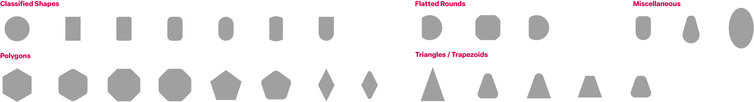
When evaluating non-round grinding requirements, the "continuity" of the shape and the "depth of concavity" are the key technical criteria:
Advantaged Machining Fields & Industries:
- Eccentric Circles & Crankshafts: Widely used in agricultural machinery (tractors, harvesters), energy-saving air compressor rotors, and pump eccentric shafts.
- Cams & Polygons: Suitable for textile machinery cams, automotive engine valve systems, and precision stamping punches (e.g., triangular, hexagonal).
- Complex Profiles: Any profile where the curve radius is larger than the grinding wheel radius and the lift variation stays within the software-simulated path can be machined.
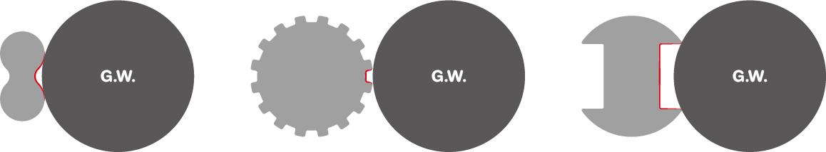
Machining Constraints:
- Concave Radius Limits: If the concave radius of the workpiece surface is smaller than the grinding wheel radius, the wheel cannot enter that area for machining.
- Sharp Internal Corners: Grinding cannot process sharp internal angles within concave grooves; a fillet equal to at least the minimum grinding wheel radius must be maintained.
- Dynamic Compensation: In non-round grinding, the wheel must move back and forth rapidly in sync with the workpiece rotation. If the shape has drastic height changes over a very short angle, it may exceed the motor’s real-time compensation speed limit. We recommend using TWCAD software for pre-machining simulation to ensure the wheel can smoothly follow the profile path.
Core Advantages: Linear Motor Drive and Cross-Slide Structure
Many business owners ask: "Traditional ball screws can also grind; why do I need linear motors?" The answer lies in equipment longevity and precision.
1. Long-Term Value of Zero Backlash and Zero Wear
Traditional ball screws rely on mechanical contact for transmission, which leads to wear and backlash under high-frequency reciprocating motion. Linear motors consist of coils and permanent magnets, offering no-wear (no attrition) characteristics. Even after long-term use, there are no backlash issues, ensuring consistently stable high-acceleration response and energy savings.
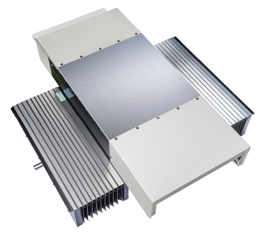
2. Cross-Slide and VDI 3441 Accuracy Standards
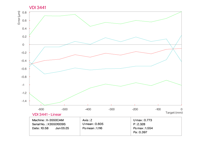
The X-Series Cross Slide integrates the X-axis and Z-axis into a single cross-slide structure. The geometric relationship between the two axes is established once during factory assembly and calibration, remaining stable even after prolonged operation. To verify this superiority, every machine undergoes rigorous VDI 3441 precision testing.
- X-axis Positioning Accuracy: Demonstrates extreme precision with a position deviation (Pa) of only approximately 0.348 μm.
- Z-axis Repeatability: Maintains a repeatability (Ps max) of about 1.554 μm even over long travel distances.
- Minimal Reversal Error: The X-axis reversal error (U max) is only 0.398 μm, proving that linear motors virtually eliminate physical backlash—a key factor in ensuring accuracy does not decay over time.
Based on this excellent mechanical foundation, combined with high-speed synchronous control of the X-axis linear motor, C-axis DD motor, and circular scales, we guarantee that grinding roundness is controlled within 3 μm, avoiding profile deterioration caused by latency.
.png)
3. Eccentric Shaft Grinding Case Study
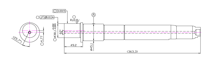
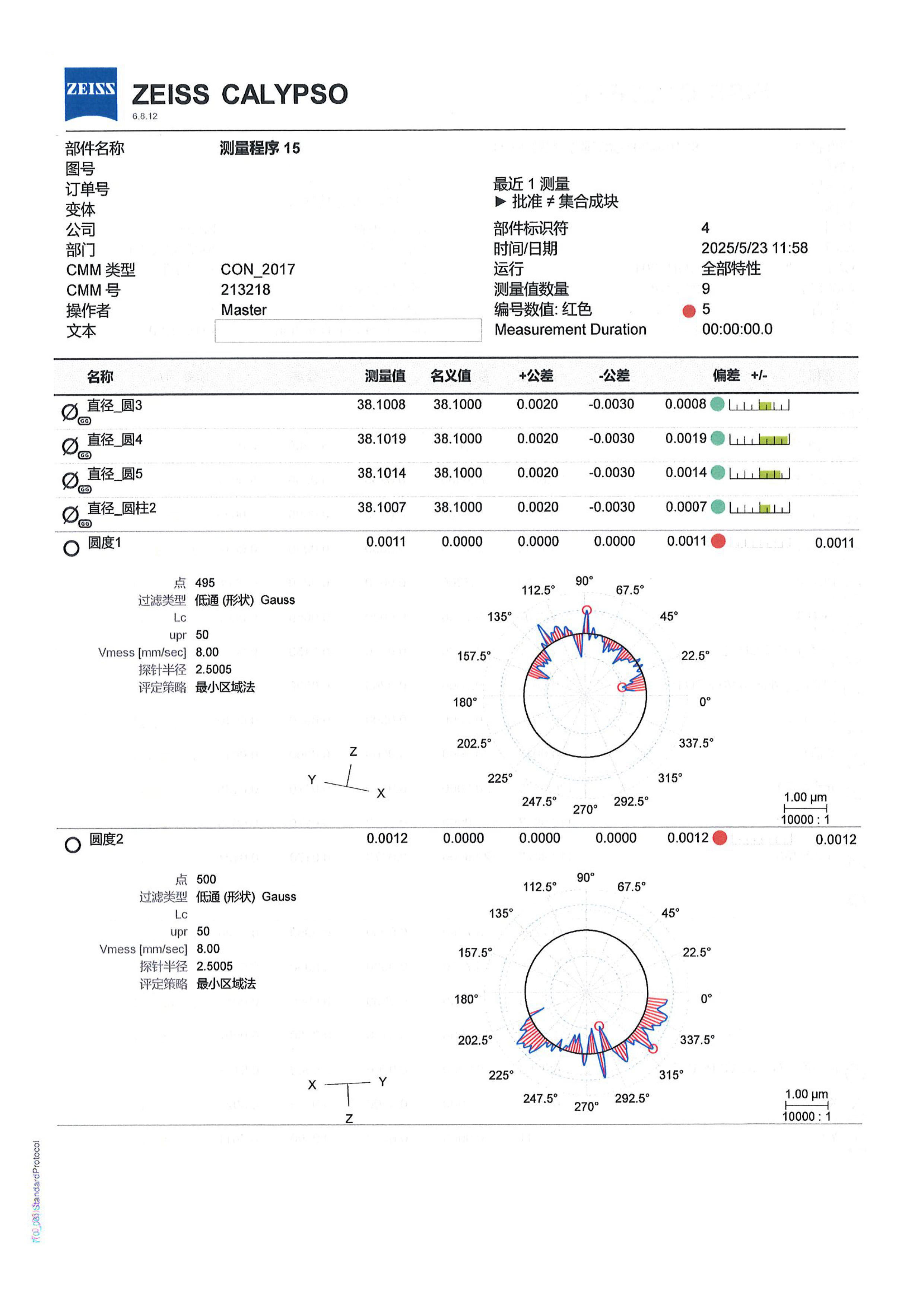
In this application, we performed grinding tests on an eccentric shaft part. Utilizing the high-speed following capability of linear motors and the stable cross-slide structure, the workpiece demonstrated superior quality under strict inspection:
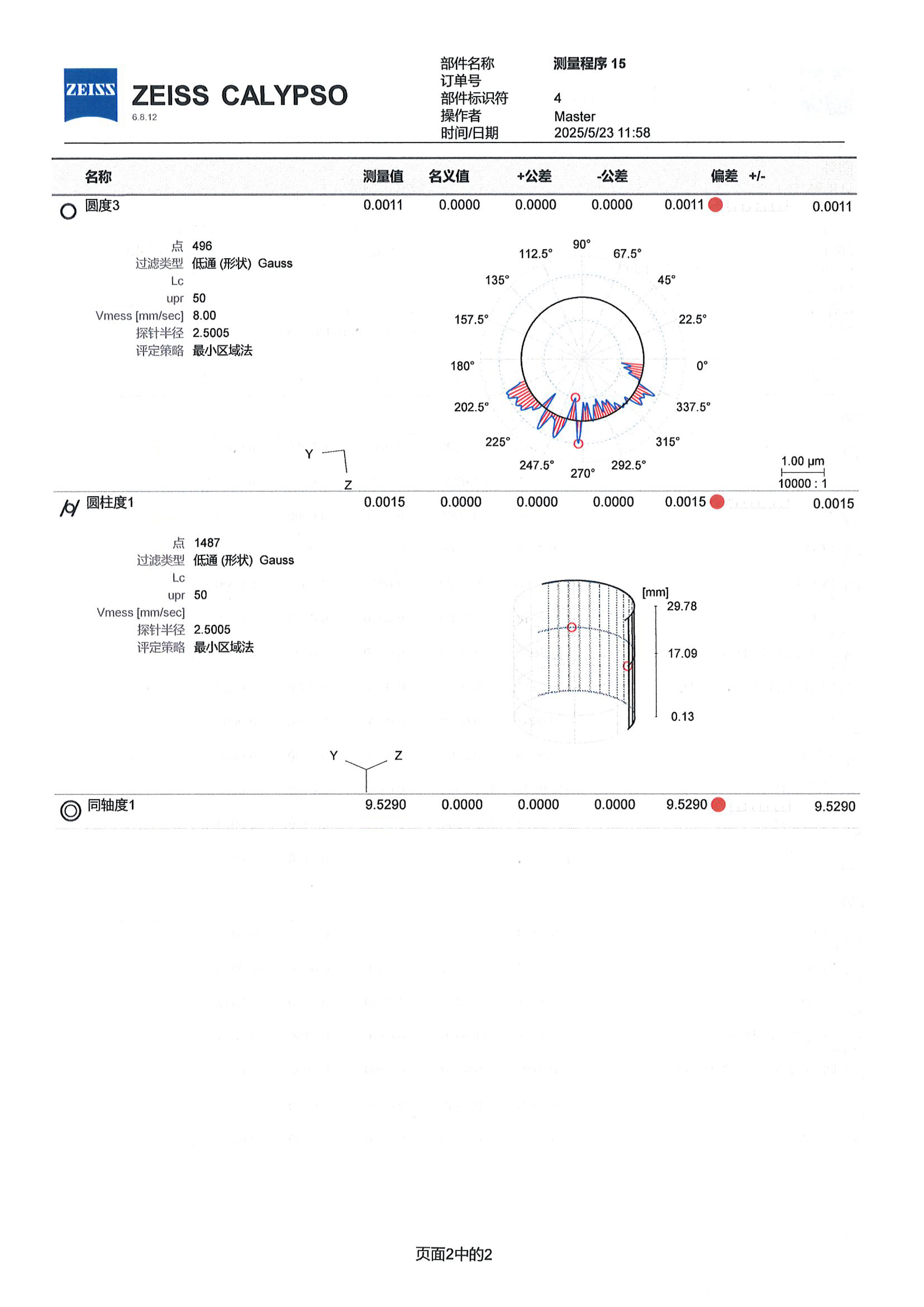
- Roundness Performance: CMM results showed roundness at multiple sections reaching 1.1 μm, 1.2 μm, and 1.1 μm.
- Cylindricity & Dimensional Control: Measured cylindricity was only 1.5 μm, with diameters precisely controlled within a tolerance range of 38.1007 mm to 38.1019 mm.
- Geometric Precision: Even with an eccentricity of 4.7645 mm (9.529 mm total throw), the X-Series CAM consistently achieved roundness better than the 3 μm target.
4. Cross-Slide Design vs. Traditional Separated Design
Compared to traditional designs where X/Z axes are mounted on different mechanisms, the cross-slide offers significant advantages in dynamic performance and long-term stability
| Item |
Cross Slide Design |
Conventional X/Z separate design |
|
Axis configuration |
X and Z-axes integrated into a single cross-slide unit |
X and Z-axes mounted on separate machine structures |
|
Geometric relationship |
Geometry established once during assembly and remains stable |
Geometry depends on alignment of multiple machine components |
|
Interpolation accuracy |
High interpolation accuracy due to concentrated kinematic chain |
Interpolation accuracy affected by cumulative structural tolerances |
|
Dynamic performance |
Low moving mass and short force transmission path |
Higher moving mass, especially on the |
|
Acceleration / deceleration |
Excellent, suitable for high-frequency motion |
Limited by axis mass and structural inertia |
|
Following error |
Very low during high-speed interpolation |
Higher following error under dynamic conditions |
|
Profile grinding capability |
Optimized for CAM, eccentric and non-round profiles |
Primarily optimized for conventional cylindrical grinding |
|
Long-term accuracy stability |
Minimal geometric drift over long-term operation |
Higher sensitivity to thermal and structural deformation |
X-Series CAM Common FAQ
Q1: What is the roundness limit for eccentric grinding?
A: Controlled within 3 μm. High-speed synchronous control allows the wheel feed to compensate in real-time based on the angle, preventing precision loss.
Q2: How long does changeover take?
A: For previously processed parts, changeover can be completed within 1 hour. Eccentric parts can be modified via built-in graphics in the HMI; non-round parts (cams, punches) use CAD/CAM files for rapid setup.
Q3: How are lift files converted into grinding paths?
A: TWCAD converts Excel lift files directly into CAD paths and grinding motions, simulating the X-C axis movements to ensure stability.
Q4: Why must non-round grinding use linear motors?
A: It requires "high-speed, continuous, real-time compensated" feed control. Linear motors reach speeds of 15,000 mm/min with no backlash to accurately follow non-round profiles.
Q5: Why is a cross-slide structure necessary?
A: It ensures the geometric relationship between axes remains stable over time, keeping interpolation paths precise and minimizing drift.
Q6: What does your after-sales service include?
A: We provide comprehensive support ranging from initial machine delivery training to real-time remote assistance.
- Initial Delivery & Education Training: We ensure that customers can independently execute production and changeover tasks.
- Real-time Remote Support: In the event of an abnormality, we can connect via video or remote diagnostics to provide immediate judgment, effectively shortening downtime.
- Warranty & Supply: Major components come with a one-year warranty. Even after the warranty period, we continue to provide technical support and spare parts supply to ensure the long-term stable operation of your equipment.
Invest in X-Series for Stable Precision Manufacturing
The X-Series CAM not only delivers roundness within 3 μm but also ensures zero wear and zero backlash through its linear motor and cross-slide design. Choosing a linear motor system enhances processing efficiency while significantly saving on the maintenance costs and risks associated with the accuracy decay of traditional equipment.
Would you like our technical team to perform a machining simulation evaluation for your specific workpiece? Contact us today!
Article Classification
Recent Articles
- The Precision Revolution in Non-Round Grinding: Why Linear Motors are the Only Choice for Crankshaft and Camshaft Machining
- NC vs CNC: The Key Role of 2NC Cylindrical Grinders in Between
- How to Choose the Right CNC Grinder: Match the Control System and Machine to Your Production Needs
- Hydrostatic Technology: The Key to Stable Centerless Grinding
- Automated Match Grinding Solutions for Hydraulic Valve Components